CMD TECHNOLOGY, INC.
CRD-5300-001, CRD-5300-002, CRD-5300-003
|
Card Type |
Hard drive controller card |
|
Processor |
RISC |
|
Maximum Onboard Memory |
128MB DRAM |
|
Hard Drives supported |
Fourteen Fast SCSI devices (5300-001) Fourteen Fast/Wide SCSI devices (5300-002) Fourteen Fast/Wide SCSI devices (5300-003) |
|
Floppy drives supported |
None |
|
Data Bus |
Fast/Wide SCSI (5300-001) Fast/Wide SCSI (5300-002) Fast/Wide/Differential SCSI (5300-003) |
|
Form-factor |
3.5 inch |
|
RAID levels supported |
0, 1, 0+1, 4 and 5, JBOD |
|
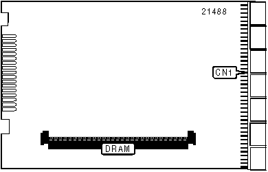
CONNECTIONS | |
|
Function |
Location |
|
Proprietary SCSI/serial/power connector to back plane |
CN1 |
|
DRAM CONFIGURATION | |
|
Size |
DRAM |
|
4MB |
(1) 1 x 36 |
|
8MB |
(1) 2 x 36 |
|
16MB |
(1) 4 x 36 |
|
32MB |
(1) 8 x 36 |
|
64MB |
(1) 16 x 36 |
|
128MB |
(1) 32 x 36 |
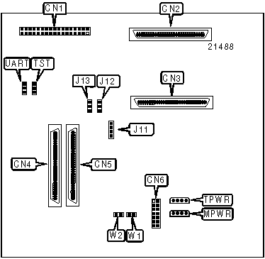
Back plane
|
CONNECTIONS | |||
|
Function |
Location |
Function |
Location |
|
Front panel connector - future use |
CN1 |
Power connector - battery |
CN6 |
|
68-pin SCSI connector - host in |
CN2 |
Termination power |
TPWR |
|
68-pin SCSI connector - host out |
CN3 |
Main power |
MPWR |
|
50/68-pin SCSI connector - channel 1 |
CN4 |
3-pin connector - UART |
UART |
|
50/68-pin SCSI connector - channel 0 |
CN5 |
|
|
|
Note: Connectors CN4 and CN5 differ on each model (see header). Controller plugs into back of back plane. | |||
|
USER CONFIGURABLE SETTINGS | |||
|
Function |
Label |
Position | |
| » |
Factory configured - do not alter (manufacturer’s test) |
TST |
N/A |
| » |
Battery connected to battery connector (CN6) |
W1 |
Open |
|
Battery connector (CN6) disabled |
W1 |
Closed | |
| » |
Factory configured - do not alter |
W2 |
Open |
|
J11 PIN-OUT (ENVIRONMENTAL CONTROL SYSTEM) | |||
|
Pin |
Description |
Pin |
Description |
|
1 |
Ground |
3 |
VCC |
|
2 |
Data |
4 |
CLK |
|
Note: This connector will be implemented in future firmware releases. | |||
|
J12 PIN-OUT (UNINTERRUPTIBLE POWER SOURCE) | |||
|
Pin |
Description |
Pin |
Description |
|
1 |
Loss of AC power |
3 |
Ground |
|
2 |
Low battery warning |
|
|
|
Note: This connector allows signals from an uninterruptible power source to be sent to CRD-5300. | |||
|
J13 PIN-OUT (EXTERNAL TEMPERATURE SENSOR) | |||
|
Pin |
Description |
Pin |
Description |
|
1 |
Power |
3 |
Ground |
|
2 |
External |
|
|
|
Note: This connector allows an external temperature sensor to replace Q1 on the back panel. | |||
|
MISCELLANEOUS TECHNICAL NOTES |
|
The CRD-5300 will not operate without an attached battery back-up or an uninterruptible power supply. Also, terminating drive buses by installing on-board resistors is not recommended because the end drive on the bus cannot be removed during a "hot swap" without leaving the bus unterminated. |