UNIDENTIFIED
W-1016
|
| |
|
Data bus: |
16-bit ISA |
|
Size: |
Half length, half-height card |
|
Hard drive supported: |
Two IDE(AT) interface drives |
|
Floppy drives supported: |
360KB, 720KB, 1.2MB, 1.44MB |
|
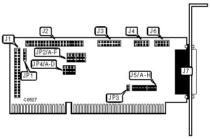
CONNECTIONS | |
|
Function |
Location |
|
34-pin data cable connector - floppy drive |
J1 |
|
40-pin control cable connector - hard drive |
J2 |
|
15-pin game port - internal |
J3 |
|
9-pin serial port 1 - internal |
J4 |
|
9-pin serial port 2 - internal |
J6 |
|
25-pin parallel port - external |
J7 |
|
4-pin connector - drive active LED |
JP1 |
|
USER CONFIGURABLE SETTINGS | |||
|
Function |
Location |
Setting | |
| » |
Parallel port unidirectional select |
JP3 |
closed |
|
Parallel port bi-directional select |
JP3 |
open | |
| » |
IDE interface address 3F6, 3F7, 1F0 - 1F7h |
JP4/A |
pins 1 & 2 closed |
|
IDE interface address 376, 377, 170 - 177h |
JP4/A |
pins 2 & 3 closed | |
| » |
IDE interface enabled |
JP4/B |
pins 2 & 3 closed |
|
IDE interface disabled |
JP4/B |
pins 1 & 2 closed | |
|
USER CONFIGURABLE SETTINGS(CONTINUED) | |||
|
Function |
Location |
Setting | |
| » |
Floppy drive interface address 3F0 - 3F7h select |
JP4/C |
pins 1 & 2 closed |
|
Floppy drive interface address 370 - 377h select |
JP4/C |
pins 2 & 3 closed | |
| » |
Floppy drive interface enabled |
JP4/D |
pins 2 & 3 closed |
|
Floppy drive interface disabled |
JP4/D |
pins 1 & 2 closed | |
|
SERIAL PORT CONFIGURATION | ||||||
|
Port 1 (J4) |
Port 2 (J6) |
JP2/A |
JP2/B |
JP2/C |
JP2/D | |
| » |
COM1 |
COM2 |
pins 2 & 3 |
pins 1 & 2 |
pins 2 & 3 |
pins 1 & 2 |
|
COM1 |
COM3 |
pins 2 & 3 |
pins 1 & 2 |
pins 2 & 3 |
pins 2 & 3 | |
|
COM1 |
COM4 |
pins 2 & 3 |
pins 1 & 2 |
pins 1 & 2 |
pins 2 & 3 | |
|
COM3 |
COM2 |
pins 1 & 2 |
pins 2 & 3 |
pins 2 & 3 |
pins 1 & 2 | |
|
COM3 |
COM4 |
pins 1 & 2 |
pins 2 & 3 |
pins 1 & 2 |
pins 2 & 3 | |
|
COM4 |
COM2 |
pins 2 & 3 |
pins 2 & 3 |
pins 2 & 3 |
pins 1 & 2 | |
|
COM4 |
COM3 |
pins 2 & 3 |
pins 2 & 3 |
pins 2 & 3 |
pins 2 & 3 | |
|
Disabled |
COM2 |
pins 1 & 2 |
pins 1 & 2 |
pins 2 & 3 |
pins 1 & 2 | |
|
Disabled |
COM3 |
pins 1 & 2 |
pins 1 & 2 |
pins 2 & 3 |
pins 2 & 3 | |
|
Disabled |
COM4 |
pins 1 & 2 |
pins 1 & 2 |
pins 1 & 2 |
pins 2 & 3 | |
|
Disabled |
Disabled |
pins 1 & 2 |
pins 1 & 2 |
pins 1 & 2 |
pins 1 & 2 | |
|
COM1 |
Disabled |
pins 2 & 3 |
pins 1 & 2 |
pins 1 & 2 |
pins 1 & 2 | |
|
COM3 |
Disabled |
pins 1 & 2 |
pins 2 & 3 |
pins 1 & 2 |
pins 1 & 2 | |
|
COM4 |
Disabled |
pins 2 & 3 |
pins 2 & 3 |
pins 1 & 2 |
pins 1 & 2 | |
|
Note: All pins designated should be placed in the closed position. | ||||||
|
SERIAL PORT INTERRUPT SELECT | ||||||||
|
Port 1 (J4) |
J5/A |
J5/B |
J5/C |
Port 2 (J6) |
J5/D |
J5/E |
J5/F | |
| » |
IRQ4 |
closed |
open |
open |
IRQ3 |
closed |
open |
open |
|
IRQ3 |
open |
closed |
open |
IRQ4 |
open |
closed |
open | |
|
IRQ5 |
open |
open |
closed |
IRQ5 |
open |
open |
closed | |
|
PARALLEL PORT CONFIGURATION | |||
|
LPT |
JP2/E |
JP2/F | |
| » |
3 |
pins 2 & 3 closed |
pins 2 & 3 closed |
|
1 |
pins 1 & 2 closed |
pins 2 & 3 closed | |
|
2 |
pins 2 & 3 closed |
pins 1 & 2 closed | |
|
Disabled |
pins 1 & 2 closed |
pins 1 & 2 closed | |
|
PARALLEL PORT INTERRUPT SELECT | |||
|
IRQ |
J5/G |
J5/H | |
| » |
IRQ7 |
closed |
open |
|
IRQ5 |
open |
closed | |