QUATECH, INC.
SMARTMUX DRI-200
|
Card Type |
I/O Card |
|
Chipset Controller |
Unidentified |
|
I/O Options |
Serial I/O |
|
Maximum Dram |
N/A |
|
CONNECTIONS | |
|
Purpose |
Location |
|
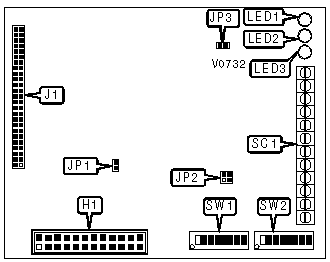
Digital module connector |
J1 |
|
Analog module header |
H1 |
|
Serial I/O and power (see table below) |
SC1 |
|
SCREW TERMINAL BLOCK CONNECTIONS | ||
|
Purpose |
Name |
Location |
|
RS-482/485 from host, positive |
FH+ |
SC1/1 |
|
RS-482/485 from host, negative |
FH- |
SC1/2 |
|
RS-422/485 to host, positive |
TH+ |
SC1/3 |
|
RS-422/485 to host, negative |
TH- |
SC1/4 |
|
RS-422/485 from bus chain, positive |
FO+ |
SC1/5 |
|
RS-422/485 from bus chain, negative |
FO- |
SC1/6 |
|
RS-422/485 to bus chain, positive |
TO+ |
SC1/7 |
|
RS-422/485 to bus chain, negative |
TO- |
SC1/8 |
|
5V DC power in |
+5V |
SC1/9 |
|
Signal ground |
GND |
SC1/10 |
|
Power switch |
ALE |
SC1/11 |
|
Reset button |
RST |
SC1/12 |
|
EEPROM WRITE ENABLE | |
|
Setting |
SW2/4 |
|
Disabled |
Off |
|
Enabled |
On |
|
FACTORY CONFIGURED-DO NOT ALTER | |
|
Switch/Jumper |
Setting |
|
SW1/1 |
On |
|
JP1 |
Open |
|
JP2 |
Pins 1 & 2, 3 & 4 closed |
|
JP3 |
Open |
|
NODE ADDRESS SELECTION | |||||||
|
Address |
SW1/2 |
SW1/3 |
SW1/4 |
SW1/5 |
SW1/6 |
SW1/7 |
SW1/8 |
|
0 |
On |
On |
On |
On |
On |
On |
On |
|
1 |
On |
On |
On |
On |
On |
On |
Off |
|
2 |
On |
On |
On |
On |
On |
Off |
On |
|
3 |
On |
On |
On |
On |
On |
Off |
Off |
|
124 |
Off |
Off |
Off |
Off |
Off |
On |
On |
|
125 |
Off |
Off |
Off |
Off |
Off |
On |
Off |
|
126 |
Off |
Off |
Off |
Off |
Off |
Off |
On |
|
127 |
Off |
Off |
Off |
Off |
Off |
Off |
Off |
|
Note: A total of 127 node address settings are available. The switches are a binary representation of the decimal node addresses. Switch 8 is the Least Significant Bit and switch 1 is the Most Significant Bit. The switches have the following decimal values: switch 8=1, 7=2, 6=4, 5=8, 4=16, 3=32, 2=64. Add the values of the off switches to obtain the correct node address. (On=0, Off=1) | |||||||
|
SERIAL PORT CONFIGURATION | |||
|
Baud Rate |
SW2/1 |
SW2/2 |
SW2/3 |
|
300 |
On |
On |
On |
|
600 |
Off |
On |
Off |
|
1200 |
On |
Off |
On |
|
2400 |
Off |
Off |
On |
|
4800 |
On |
On |
Off |
|
9600 |
Off |
On |
Off |
|
19200 |
On |
Off |
Off |
|
38400 |
Off |
Off |
Off |
|
BUS TYPE SELECTION | |
|
Bus Type |
SW2/5 |
|
Multi-Drop |
On |
|
Daisy Chain |
Off |
|
RESISTOR SETUP FOR SERIAL I/O | ||||||
|
Usage |
Bias from Host |
Match from Host |
Match Out |
SW2/6 |
SW2/7 |
SW2/8 |
|
End of Multi-Drop Chain Daisy Chain Node |
Yes |
Yes |
Yes |
On |
On |
On |
|
Multi-Drop Node |
No |
No |
No |
Off |
Off |
Off |
|
DIAGNOSTIC LEDS | |||
|
LED |
Color |
Status |
Condition |
|
LED1 |
Green |
Flashing |
Sending data |
|
LED2 |
Green |
Flashing |
Receiving data |
|
LED3 |
Red |
On |
Power on |
|
LED3 |
Red |
Flashing |
Startup or hardware failure |
|
LED3 |
Red |
Off |
Power off or hardware failure |
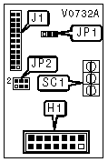
ARI-12G DAUGHTERBOARD
|
CONNECTIONS | |
|
Purpose |
Location |
|
Analog module connector |
J1 |
|
Mainboard header |
H1 |
|
Power (see table below) |
SC1 |
|
SCREW TERMINAL BLOCK CONNECTIONS | ||
|
Purpose |
Name |
Location |
|
+12V DC power in |
+12V |
SC1/1 |
|
-12V DC power in |
-12V |
SC1/2 |
|
Signal ground |
GND |
SC1/3 |
|
A/D CONVERTER MODE SELECTION | |
|
Mode |
JP1 |
|
Bipolar mode |
Pins 1 & 2 closed |
|
Unipolar mode |
Pins 2 & 3 closed |
|
D/A CONVERTER MODE SELECTION | |
|
Mode |
JP2 |
|
Bipolar mode |
Pins 1 & 2, 4 & 5 closed |
|
Unipolar mode |
Pins 2 & 3, 5 & 6 closed |