LANNER ELECTRONICS, INC.
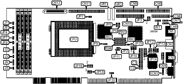
AP-60IFA
|
Device Type |
Mainboard |
|
Processor |
Pentium Pro |
|
Processor Speed |
150/166/180/200MHz |
|
Chip Set |
Intel |
|
Video Chip Set |
Chips & Technologies |
|
Maximum Onboard Memory |
512MB (EDO supported) |
|
Maximum Video Memory |
2MB |
|
Cache |
256KB (located on Pentium Pro CPU) |
|
BIOS |
AMI/Award |
|
Dimensions |
Unidentified |
|
I/O Options |
Floppy drive interface, green PC connector, IDE interfaces (2), SCSI interface, Wide Ultra SCSI interface, parallel port, PS/2 mouse port, serial ports (2), VGA port, IR connector, USB connectors (2), flat panel connectors (2) |
|
NPU Options |
None |
|
CONNECTIONS | |||
|
Purpose |
Location |
Purpose |
Location |
|
Flat panel connector |
C1 |
SCSI interface |
CN11 |
|
Flat panel connector |
C2 |
Wide Ultra SCSI interface |
CN12 |
|
VGA port |
CN1 |
IDE interface LED |
J1 |
|
PS/2 mouse port |
CN2 |
Power LED & keylock |
J2 |
|
Serial port 1 |
CN3 |
Turbo LED |
J3 |
|
Serial port 2 |
CN4 |
Speaker |
J4 |
|
Floppy drive interface |
CN5 |
Reset switch |
J5 |
|
Parallel port |
CN6 |
SCSI interface LED |
J6 |
|
USB connector 1 |
CN7 |
Green PC connector |
JP4 |
|
USB connector 2 |
CN8 |
IR connector |
IR1 |
|
IDE interface 1 |
CN9 |
Auxiliary keyboard connector |
KCN1 |
|
IDE interface 2 |
CN10 | ||
|
USER CONFIGURABLE SETTINGS | |||
|
Function |
Label |
Position | |
|
SCSI termination enabled |
JP1 |
Open | |
|
SCSI termination disabled |
JP1 |
Closed | |
|
» |
VEE voltage select +12v - +35v |
JP5 |
Pins 2 & 3 closed |
|
VEE voltage select -12v - -34v |
JP5 |
Pins 1 & 2 closed | |
|
» |
Contrast voltage enabled |
JP6 |
Pins 1 & 2 closed |
|
VEE voltage enabled |
JP6 |
Pins 2 & 3 closed | |
|
» |
Factory configured - do not alter |
JP12 |
Open |
|
» |
Factory configured - do not alter |
JP13 |
Pins 2 & 3, 5 & 6, 8 & 9 closed |
|
» |
Factory configured - do not alter |
JP14 |
Pins 1 & 2, 3 & 4, 5 & 6, 7 & 8, 9 & 10, 11 & 12 closed |
|
» |
PS/2 mouse IRQ12 enabled |
JP15 |
Closed |
|
PS/2 mouse IRQ12 disabled |
JP15 |
Open | |
|
» |
Flash BIOS voltage select 5v |
JP20 |
Pins 2 & 3 closed |
|
Flash BIOS voltage select 12v |
JP20 |
Pins 1 & 2 closed | |
|
» |
Factory configured - do not alter |
RN1 |
Unidentified |
|
» |
Factory configured - do not alter |
RN2 |
Unidentified |
|
» |
Factory configured - do not alter |
RN3 |
Unidentified |
|
» |
Factory configured - do not alter |
RN4 |
Unidentified |
|
» |
Factory configured - do not alter |
VR1 |
Unidentified |
|
» |
Factory configured - do not alter |
VR1 |
Unidentified |
|
SIMM CONFIGURATION | ||
|
Size |
Bank 0 |
Bank 1 |
|
8MB |
(2) 1M x 36 |
None |
|
16MB |
(2) 2M x 36 |
None |
|
16MB |
(2) 1M x 36 |
(2) 1M x 36 |
|
24MB |
(2) 2M x 36 |
(2) 1M x 36 |
|
32MB |
(2) 4M x 36 |
None |
|
32MB |
(2) 2M x 36 |
(2) 2M x 36 |
|
40MB |
(2) 4M x 36 |
(2) 1M x 36 |
|
48MB |
(2) 4M x 36 |
(2) 2M x 36 |
|
64MB |
(2) 8M x 36 |
None |
|
64MB |
(2) 4M x 36 |
(2) 4M x 36 |
|
72MB |
(2) 8M x 36 |
(2) 1M x 36 |
|
80MB |
(2) 8M x 36 |
(2) 2M x 36 |
|
96MB |
(2) 8M x 36 |
(2) 4M x 36 |
|
128MB |
(2) 8M x 36 |
(2) 8M x 36 |
|
128MB |
(2) 16M x 36 |
None |
|
136MB |
(2) 16M x 36 |
(2) 1M x 36 |
|
144MB |
(2) 16M x 36 |
(2) 2M x 36 |
|
160MB |
(2) 16M x 36 |
(2) 4M x 36 |
|
192MB |
(2) 16M x 36 |
(2) 8M x 36 |
|
256MB |
(2) 32M x 36 |
None |
|
256MB |
(2) 16M x 36 |
(2) 16M x 36 |
|
264MB |
(2) 32M x 36 |
(2) 1M x 36 |
|
272MB |
(2) 32M x 36 |
(2) 2M x 36 |
|
288MB |
(2) 32M x 36 |
(2) 4M x 36 |
|
320MB |
(2) 32M x 36 |
(2) 8M x 36 |
|
384MB |
(2) 32M x 36 |
(2) 16M x 36 |
|
512MB |
(2) 32M x 36 |
(2) 32M x 36 |
|
Note: Board accepts EDO memory. | ||
|
CACHE CONFIGURATION |
|
Note: 256KB cache is located on the Pentium Pro CPU. |
|
VIDEO MEMORY CONFIGURATION |
|
Note: Board accepts 1MB/2MB video memory. The location is unidentified. |
|
CPU SPEED SELECTION | ||||||
|
CPU speed |
Clock speed |
Multiplier |
JP7 |
JP8 |
JP16 |
JP18 |
|
150MHz |
60MHz |
2.5x |
Open |
Closed |
1 & 2, 3 & 4, 5 & 6 |
1 & 2 |
|
166MHz |
66MHz |
2.5x |
Closed |
Open |
1 & 2, 3 & 4, 5 & 6 |
Open |
|
180MHz |
60MHz |
3x |
Open |
Closed |
1 & 2, 3 & 4, 7 & 8 |
1 & 2 |
|
200MHz |
66MHz |
3x |
Closed |
Open |
1 & 2, 3 & 4, 7 & 8 |
Open |
|
Note: Pins designated should be in the closed position. | ||||||
|
FLAT PANEL SELECTION | ||
|
Setting |
JP3 | |
|
1024 x 768 DSTN |
Pins 1 & 2, 3 & 4, 5 & 6 closed | |
|
1280 x 1024 TFT |
Pins 3 & 4, 5 & 6 closed | |
|
640 x 480 DSTN |
Pins 1 & 2, 5 & 6 closed | |
|
800 x 600 DSTN |
Pins 5 & 6 closed | |
|
640 x 480 Sharp TFT |
Pins 1 & 2, 3 & 4 closed | |
| » |
640 x 480 18 bit TFT |
Pins 3 & 4 closed |
|
1024 x 768 TFT |
Pins 1 & 2 closed | |
|
800 x 600 TFT |
Open | |
|
WATCHDOG TIMER ACTIVE SELECTION | ||
|
Time out |
JP10 | |
|
.5 sec |
Pins 2 & 3 closed | |
|
1 sec |
Pins 5 & 6 closed | |
|
2 sec |
Pins 8 & 9 closed | |
| » |
4 sec |
Pins 11 & 12 closed |
|
8 sec |
Pins 10 & 11 closed | |
|
16 sec |
Pins 7 & 8 closed | |
|
32 sec |
Pins 4 & 5 closed | |
|
64 sec |
Pins 1 & 2 closed | |
|
WATCHDOG TIMER ACTIVE SELECTION | ||
|
Time out |
JP11 | |
| » |
Reset system |
Pins 1 & 2 closed |
|
NMI system |
Pins 2 & 3 closed | |
|
Disabled |
Open | |
|
SCSI SELECTION | |||
|
Setting |
JP2 |
JP9 | |
| » |
8 bit |
Open |
Pins 1 & 2 closed |
|
Wide |
Closed |
Pins 1 & 2 closed | |
|
Ultra Wide |
Closed |
Pins 2 & 3 closed | |