TEXAS INSTRUMENTS
SYSTEM SP1000E
|
Processor |
80386DX |
|
Processor Speed |
16MHz |
|
Chip Set |
AMD |
|
Max. onboard DRAM |
4MB |
|
Cache |
None |
|
BIOS |
AMD |
|
Dimensions |
355mm x 304mm |
|
I/O Options |
32-bit proprietary bus slot |
|
NPU Options |
80387DX |
|
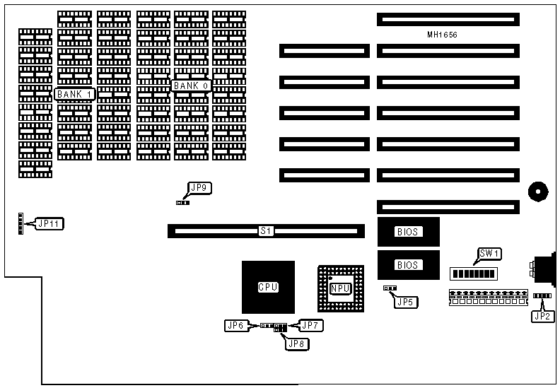
CONNECTIONS | |||
|
Purpose |
Location |
Purpose |
Location |
|
External battery |
JP2 |
32-bit proprietary bus slot |
S1 |
|
Control panel connector |
JP11 | ||
|
USER CONFIGURABLE SETTINGS | |||
|
Function |
Jumper/Switch |
Position | |
| » |
Monitor type select CGA |
SW1/switch 5 |
Off |
|
Monitor type select monochrome or EGA |
SW1/switch 5 |
On | |
| » |
CPU speed select smart mode |
SW1/switch 6 |
On |
| » |
CPU speed select 16MHz |
SW1/switch 6 |
Off |
| » |
Factory configured - do not alter |
SW1/switch 7 |
Off |
|
Note:In the smart mode, the processor slows down during accesses to the diskette drive. | |||
|
BIOS CONFIGURATION | ||||||
|
BIOS |
JP5 |
SW1/switch 1 |
SW1/switch 2 |
SW1/switch 3 |
SW1/switch 4 | |
| » |
27156 |
pins 1 & 2 |
On |
On |
Off |
Off |
|
27128 |
pins 1 & 2 |
Off |
Off |
On |
On | |
|
27512 |
pins 2 & 3 |
Off |
Off |
On |
On | |
|
Note:Pins designated should be in the closed position. | ||||||
|
NPU CONFIGURATION | |||
|
NPU |
JP6 |
JP7 |
JP8 |
|
Enabled |
pins 2 & 3 closed |
pins 2 & 3 closed |
pins 2 & 3 closed |
|
Disabled |
pins 2 & 3 closed |
pins 2 & 3 closed |
pins 2 & 3 closed |
|
SYSTEM DRAM CONFIGURATION | |||
|
Size |
Bank 0 |
Bank 1 |
JP9 |
|
2MB |
(16) 411000 |
NONE |
pins 2 & 3 closed |
|
4MB |
(16) 411000 |
(16) 411000 |
pins 1 & 2 closed |
|
SYSTEM MEMORY MODE CONFIGURATION | |||
|
Base |
BIOS |
External Memory |
SW1/8 |
|
640KB |
Normal |
0KB |
On |
|
640KB |
Loaded high |
0KB |
Off |
|
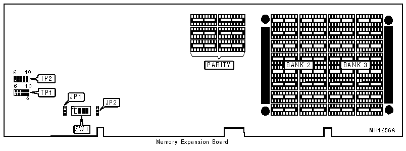
USER CONFIGURABLE SETTINGS FOR EXTERNAL MEMORY | |||
|
Function |
Jumper |
Position | |
| » |
Factory configured - do not alter |
JP1 |
pins 1 & 2 closed |
| » |
Factory configured - do not alter |
JP2 |
pins 2 & 3 closed |
| » |
Factory configured - do not alter |
TP1 |
pins 3 & 8, 4 & 9 closed |
| » |
Factory configured - do not alter |
TP2 |
pins 3 & 8, 4 & 9 closed |
|
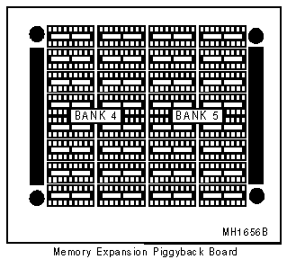
EXTERNAL MEMORY CONFIGURATION | ||||
|
Size |
Bank 2 |
Bank 3 |
Bank 4 |
Bank 5 |
|
2MB |
(16) 411000 |
NONE |
NONE |
NONE |
|
4MB |
(16) 411000 |
(16) 411000 |
NONE |
NONE |
|
6MB |
(16) 411000 |
(16) 411000 |
(16) 411000 |
NONE |
|
8MB |
(16) 411000 |
(16) 411000 |
(16) 411000 |
(16) 411000 |
|
EXTERNAL MEMORY SWITCH CONFIGURATION | |||
|
Size |
SW1/switch 1 |
SW1/switch 2 |
SW1/switch 3 |
|
2MB |
On |
On |
On |
|
4MB |
Off |
On |
On |
|
6MB |
Off |
Off |
On |
|
8MB |
Off |
Off |
Off |