XINETRON, INC.
XINET LS2202/LS2203
|
Processor |
80286 |
|
Processor Speed |
20MHz |
|
Chip Set |
C & T |
|
Max. Onboard DRAM |
4MB |
|
SRAM Cache |
None |
|
BIOS |
Award |
|
Dimensions |
330mm x 218mm |
|
I/O Options |
AUI ethernet interface, BNC ethernet interface, floppy drive interface, IDE interface, parallel port, serial ports (2), VGA port |
|
NPU Options |
80287 |
|
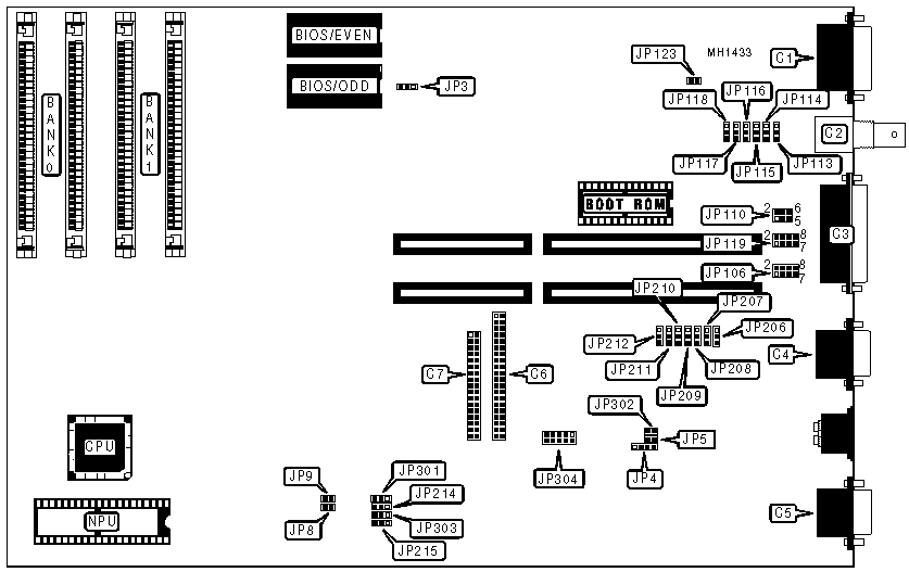
CONNECTIONS | |||
|
Purpose |
Location |
Purpose |
Location |
|
AUI ethernet interface |
C1 |
IDE interface |
C6 |
|
BNC ethernet interface |
C2 |
Floppy drive interface |
C7 |
|
Parallel port |
C3 |
External battery |
JP4 |
|
Serial port (COM2) |
C4 |
Reset switch |
JP5 |
|
Serial port (COM1) |
C5 |
VGA connection |
JP304 |
|
USER CONFIGURABLE SETTINGS | |||
|
Function |
Jumper |
Position | |
| » |
BIOS type select 27256 |
JP3 |
pins 1 & 2 closed |
|
BIOS type select 27128 |
JP3 |
pins 2 & 3 closed | |
| » |
Monitor type select monochrome |
JP8 |
Open |
|
Monitor type select color |
JP8 |
Closed | |
| » |
CPU speed keyboard selectable |
JP9 |
Closed |
|
CPU speed "normal" |
JP9 |
Open | |
| » |
Floppy drive interface enabled |
JP207 |
pins 2 & 3 closed |
|
Floppy drive interface disabled |
JP207 |
pins 1 & 2 closed | |
| » |
IDE interface enabled |
JP214 & JP215 |
pins 2 & 3 closed |
|
IDE interface disabled |
JP214 & JP215 |
pins 1 & 2 closed | |
|
SERIAL PORT CONFIGURATION | |||||
|
Port 1 (C3) |
Port 2 (C4) |
JP208 |
JP209 |
JP210 | |
| » |
Enabled |
Enabled |
pins 2 & 3 closed |
pins 2 & 3 closed |
pins 2 & 3 closed |
|
Enabled |
Disabled |
pins 2 & 3 closed |
pins 1 & 2 closed |
pins 2 & 3 closed | |
|
Disabled |
Enabled |
pins 2 & 3 closed |
pins 2 & 3 closed |
pins 1 & 2 closed | |
|
Disabled |
Disabled |
pins 1 & 2 closed |
pins 1 & 2 closed |
pins 1 & 2 closed | |
|
PARALLEL PORT (C3) CONFIGURATION | |||
|
LPT |
I/O Address |
JP211 |
JP212 |
|
LPT 1 |
3BCh |
pins 2 & 3 closed |
pins 1 & 2 closed |
|
LPT 2 |
378h |
pins 2 & 3 closed |
pins 2 & 3 closed |
|
LPT 3 |
278h |
pins 1 & 2 closed |
pins 2 & 3 closed |
|
Disabled |
N/A |
pins 1 & 2 closed |
pins 1 & 2 closed |
|
VIDEO CONFIGIURATION | |||
|
Function |
JP301 |
JP303 | |
| » |
Onboard video enabled |
pins 2 & 3 closed |
pins 1 & 2 closed |
|
Onboard video disabled |
pins 1 & 2 closed |
pins 2 & 3 closed | |
|
ETHERNET NETWORK INTERRUPT CONFIGURATION | |||
|
Function |
Jumper |
Position | |
| » |
Interrupt request select IRQ3 |
JP106 |
pins 3 & 4 closed |
|
Interrupt request select IRQ2 |
JP106 |
pins 1 & 2 closed | |
|
Interrupt request select IRQ4 |
JP106 |
pins 5 & 6 closed | |
|
Interrupt request select IRQ5 |
JP106 |
pins 7 & 8 closed | |
|
ETHERNET I/O BASE ADDRESS CONFIGURATION | |||
|
Function |
Jumper |
Position | |
| » |
I/O base address 320h |
JP119 |
pins 3 & 4 closed |
|
I/O base address 300h |
JP119 |
pins 1 & 2 closed | |
|
I/O base address 340h |
JP119 |
pins 5 & 6 closed | |
|
I/O base address 360h |
JP119 |
pins 7 & 8 closed | |
|
ETHERNET BOOT ROM MEMORY ADDRESS CONFIGURATION | |||
|
Function |
Jumper |
Position | |
| » |
Boot ROM memory address CC000h |
JP110 |
pins 3 & 4 closed |
|
Boot ROM memory address C8000h |
JP110 |
pins 1 & 2 closed | |
|
Boot ROM memory address D0000h |
JP110 |
pins 5 & 6 closed | |
|
ETHERNET CABLE TYPE CONFIGURATION | ||
|
Type |
JP113-JP118 |
JP123 |
|
BNC |
pins 2 & 3 closed |
Closed |
|
AUI tranceiver via 9-pin |
pins 1 & 2 closed |
Open |
|
DRAM CONFIGURATION | ||
|
Size |
Bank 0 |
Bank 1 |
|
512KB |
(2) 256K x 9 |
NONE |
|
1MB |
(2) 256K x 9 |
(2) 256K x 9 |
|
2MB |
(2) 1M x 9 |
NONE |
|
4MB |
(2) 1M x 9 |
(2) 1M x 9 |