UNIDENTIFIED
386 SIS CACHE
|
Processor |
80386 |
|
Processor Speed |
25/33MHz |
|
Chip Set |
SIS |
|
Video Chip Set |
None |
|
Maximum Onboard Memory |
16MB (8MB on external memory card) |
|
Maximum Video Memory |
None |
|
Cache |
32/64/128KB |
|
BIOS |
AMI |
|
Dimensions |
330mm x 218mm |
|
I/O Options |
External memory card |
|
NPU Options |
80387/3167 |
|
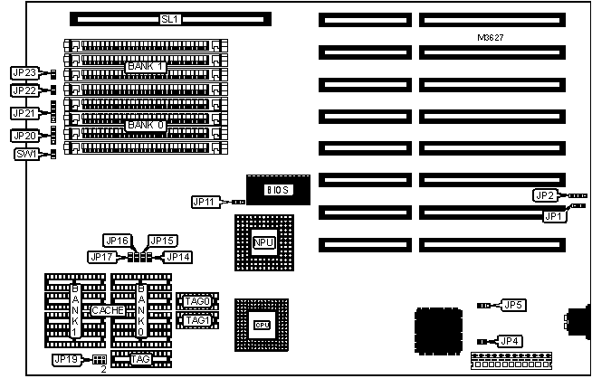
CONNECTIONS | |||
|
Purpose |
Location |
Purpose |
Location |
|
External battery |
JP2 |
Turbo LED |
JP23 |
|
Speaker |
JP20 |
External memory card |
SL1 |
|
Power LED & keylock |
JP21 |
Reset switch |
SW1 |
|
Turbo switch |
JP22 | ||
|
USER CONFIGURABLE SETTINGS | |||
|
Function |
Label |
Position | |
|
» |
CMOS memory normal operation |
JP1 |
Pins 2 & 3 closed |
|
CMOS memory clear |
JP1 |
Pins 1 & 2 closed | |
|
Monitor type select color |
JP4 |
Closed | |
|
Monitor type select monochrome |
JP4 |
Open | |
|
» |
Power good signal detect from power supply |
JP5 |
Pins 1 & 2 closed |
|
Power good signal detect from board |
JP5 |
Pins 2 & 3 closed | |
|
NPU not installed |
JP11 |
Pins 1 & 2 closed | |
|
NPU installed |
JP11 |
Pins 2 & 3 closed | |
|
DRAM CONFIGURATION | ||||
|
Size |
Bank 0 |
Bank 1 |
Bank 2 |
Bank 3 |
|
1MB |
(4) 256K x 9 |
None |
None |
None |
|
2MB |
(4) 256K x 9 |
(4) 256K x 9 |
None |
None |
|
4MB |
(4) 1M x 9 |
None |
None |
None |
|
8MB |
(4) 1M x 9 |
(4) 1M x 9 |
None |
None |
|
12MB |
(4) 1M x 9 |
(4) 1M x 9 |
(4) 1M x 9 |
None |
|
16MB |
(4) 1M x 9 |
(4) 1M x 9 |
(4) 1M x 9 |
(4) 1M x 9 |
|
Note: Banks 2 & 3 are located on the external memory card. | ||||
|
CACHE CONFIGURATION (EXTERNAL) | ||
|
Size |
Bank 0 |
Bank 1 |
|
32KB |
None |
(4) 8K x 8 |
|
64KB |
(4) 8K x 8 |
(1) 8K x 8 |
|
128KB |
(4) 32K x 8 |
None |
|
CACHE TAG CONFIGURATION (EXTERNAL) | |||
|
Size |
TAG |
TAG 0 |
TAG 1 |
|
32KB |
None |
(1) 16K x 4 |
(1) 16K x 4 |
|
64KB |
None |
(1) 16K x 4 |
(1) 16K x 4 |
|
128KB |
(1) 32K x 8 |
None |
None |
|
CACHE JUMPER CONFIGURATION (EXTERNAL) | |
|
Size |
JP19 |
|
32KB |
Pins 1 & 2 closed |
|
64KB |
Pins 3 & 4 closed |
|
128KB |
Pins 5 & 6 closed |
|
CACHE JUMPER CONFIGURATION (INTERNAL) | ||||
|
Size |
JP14 |
JP15 |
JP16 |
JP17 |
|
128KB internal enabled |
Closed |
Closed |
Closed |
Closed |
|
128KB internal disabled |
Open |
Open |
Open |
Open |
|
Note: To use internal 128KB cache, remove all external cache chips. Turn system on and press INS key. Then press F1 and enable cache in BIOS setup. | ||||