INTERPHASE CORPORATION
4811 E/FDDI ADAPTER (DAS MIC CONNECTION)
|
Card Type |
Network Interface Card |
|
NIC Type |
FDDI |
|
Maximum Onboard Memory |
128KB |
|
Boot ROM |
Unidentified |
|
Network Transfer Rate |
100Mbps |
|
Topology |
Ring, Peer-Peer |
|
Wiring Type |
Fiber optic cable |
|
Data Bus |
32-bit EISA |
|
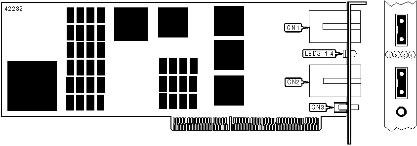
CONNECTIONS | |||
|
Function |
Label |
Function |
Label |
|
Fiber optic connector - MIC (Phy A) |
CN1 |
Optical Bypass Switch jack |
CN3 |
|
Fiber optic connector - MIC (Phy B) |
CN2 | ||
|
Note: Type A (Phy A) or Type B (Phy B) connectors are designated by a labeled key in the side of the male MIC. CN1 is keyed for an A type connector, and CN2 is keyed for a B type connector. | |||
|
DIAGNOSTIC LED(S) | ||||
|
LED1 (Yellow) |
LED2 (Yellow) |
LED3 (Green) |
LED3 (Green) |
Condition |
|
Off |
Off |
Off |
On |
Power to card |
|
On |
Off |
Off |
On |
Power on diagnostics |
|
Off |
Off |
On |
On |
Diagnostics passed |
|
Off |
Blinking |
On |
On |
CB Running |
|
Off |
Off |
Blinking |
On |
RC Running |
|
Off |
On |
Blinking |
On |
Ring connection good |
|
On |
Off |
Off |
On |
Adapter Failure |
|
Note: Definitions of "CB" and "RC" are unidentified. | ||||
|
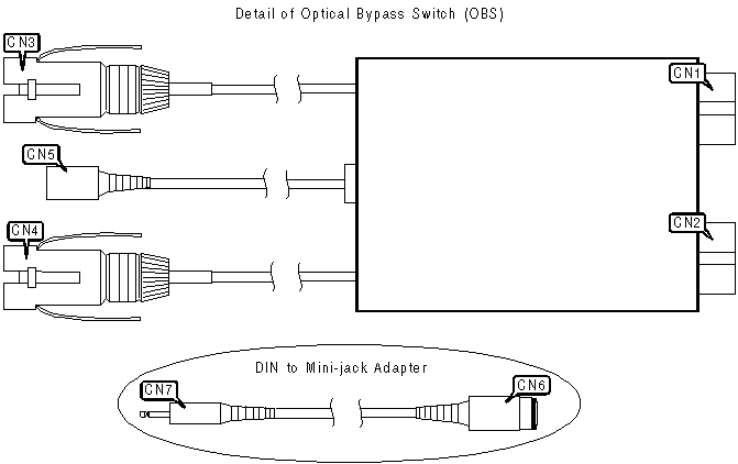
CONNECTIONS | |||
|
Function |
Label |
Function |
Label |
|
Fiber optic connector - MIC (Phy A) |
CN1 |
6-pin DIN socket (Optical Bypass Switch) |
CN5 |
|
Fiber optic connector - MIC (Phy B) |
CN2 |
6-pin DIN socket (Optical Bypass Switch) |
CN6 |
|
Fiber optic connector - MIC (male) (Phy A) |
CN3 |
Mini-jack (Optical Bypass Switch) |
CN7 |
|
Fiber optic connector - MIC (male) (Phy B) |
CN4 | ||
|
Note: Type A (Phy A) or Type B (Phy B) connectors are designated by a labeled key in the side of the male MIC. CN1 and CN3 are keyed for A type connectors, and CN2 and CN4 are keyed for B type connectors. The Dual Attachment Station - MIC version of the 4811 E/FDDI Adapter also requires an adapter cable (see "DIN to Mini-jack Adapter" in above diagram) in order to properly connect the Optical Bypass Switch. | |||