3COM CORPORATION
US ROBOTICS NETSERVER I-MODEM/16
|
Card Type |
Modem (asynchronous) |
|
Chip Set |
Unidentified |
|
Maximum Modem Rate |
33.6Kbps |
|
Maximum Fax Rate |
14.4Kbps |
|
Data Modulation Protocol |
Unidentified |
|
Fax Modulation Protocol |
Unidentified |
|
Error Correction/Compression |
Unidentified |
|
Fax Class |
Class I & II |
|
Data Bus |
External |
|
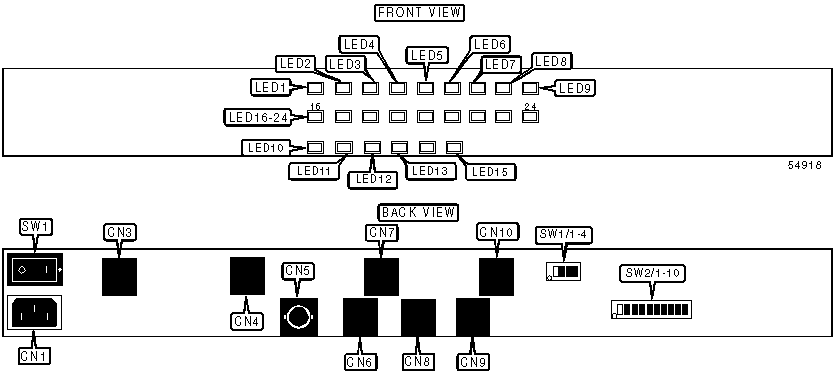
CONNECTIONS | ||||||
|
Function |
Label |
Function |
Label | |||
|
DC power |
CN1 |
RJ-45 jack channel 5/6 |
CN7 | |||
|
RJ-45 jack channel 1/2 |
CN3 |
RJ-45 auxiliary connector |
CN8 | |||
|
RJ-45 jack channel 3/4 |
CN4 |
RJ-45 console connector |
CN9 | |||
|
BNC network connector |
CN5 |
RJ-45 jack channel 7/8 |
CN10 | |||
|
RJ-45 network connector |
CN6 |
Power switch |
SW1 | |||
Note: CN3, CN4, CN7, CN10 accept either RJ-11 or RJ-45 connectors. | ||||||
|
USER CONFIGURABLE SETTINGS | ||
|
Setting |
Label |
Position |
|
Load defaults from NVRAM |
SW1/1 |
Off |
|
Load defaults from ROM |
SW1/1 |
On |
|
Command odd set recognition disabled |
SW1/2 |
Off |
|
Command odd set recognition enabled |
SW1/2 |
On |
|
Factory configured - do not alter |
SW1/3 |
Unidentified |
|
Factory configured - do not alter |
SW1/4 |
Unidentified |
|
Use software configured baud rate |
SW2/3 |
Off |
|
Force DIP switch rate |
SW2/3 |
On |
|
Normal flash memory operation |
SW2/4 |
Off |
|
Erase flash memory on boot-up |
SW2/4 |
On |
|
Factory configured - do not alter |
SW2/5-10 |
Unidentified |
|
CONSOLE PORT BAUD RATE | ||
|
Rate |
SW2/1 |
SW2/2 |
|
9600bps |
Off |
Off |
|
19.2Kbps |
Off |
On |
|
38.4Kbps |
On |
Off |
|
57.6Kbps |
On |
On |
|
DIAGNOSTIC LED(S) | |||
|
LED |
Color |
Status |
Condition |
|
LED1 |
Off |
Off |
Power off |
|
LED1 |
Green |
On |
Power on |
|
LED1 |
Red |
On |
Critical failure |
|
LED2 |
Off |
Off |
Channel 1 idle |
|
LED2 |
Green |
On |
Channel 1 on-line |
|
LED2 |
Green |
Blinking |
Channel 1 testing data link layer |
|
LED2 |
Yellow |
Blinking (8 times/sec.) |
Channel 1 searching for U interface |
|
LED2 |
Yellow |
Blinking (1 times/sec.) |
Channel 1 searching for S/T interface |
|
LED2 |
Yellow |
On |
Channel 1 dialing |
|
LED2 |
Red |
On |
Channel 1 U interface not found |
|
LED2 |
Red |
Blinking |
Channel 1 incorrect SPID |
|
LED3 |
Off |
Off |
Channel 2 idle |
|
LED3 |
Green |
On |
Channel 2 on-line |
|
LED3 |
Green |
Blinking |
Channel 2 testing data link layer |
|
LED3 |
Yellow |
Blinking (8 times/sec.) |
Channel 2 searching for U interface |
|
LED3 |
Yellow |
Blinking (1 times/sec.) |
Channel 2 searching for S/T interface |
|
LED3 |
Yellow |
On |
Channel 2 dialing |
|
LED3 |
Red |
On |
Channel 2 U interface not found |
|
LED3 |
Red |
Blinking |
Channel 2 incorrect SPID |
|
DIAGNOSTIC LED(S) (CON’T) | |||
|
LED |
Color |
Status |
Condition |
|
LED4 |
Off |
Off |
Channel 3 idle |
|
LED4 |
Green |
On |
Channel 3 on-line |
|
LED4 |
Green |
Blinking |
Channel 3 testing data link layer |
|
LED4 |
Yellow |
Blinking (8 times/sec.) |
Channel 3 searching for U interface |
|
LED4 |
Yellow |
Blinking (1 times/sec.) |
Channel 3 searching for S/T interface |
|
LED4 |
Yellow |
On |
Channel 3 dialing |
|
LED4 |
Red |
On |
Channel 3 U interface not found |
|
LED4 |
Red |
Blinking |
Channel 3 incorrect SPID |
|
LED5 |
Off |
Off |
Channel 4 idle |
|
LED5 |
Green |
On |
Channel 4 on-line |
|
LED5 |
Green |
Blinking |
Channel 4 testing data link layer |
|
LED5 |
Yellow |
Blinking (8 times/sec.) |
Channel 4 searching for U interface |
|
LED5 |
Yellow |
Blinking (1 times/sec.) |
Channel 4 searching for S/T interface |
|
LED5 |
Yellow |
On |
Channel 4 dialing |
|
LED5 |
Red |
On |
Channel 4 U interface not found |
|
LED5 |
Red |
Blinking |
Channel 4 incorrect SPID |
|
LED6 |
Off |
Off |
Channel 5 idle |
|
LED6 |
Green |
On |
Channel 5 on-line |
|
LED6 |
Green |
Blinking |
Channel 5 testing data link layer |
|
LED6 |
Yellow |
Blinking (8 times/sec.) |
Channel 5 searching for U interface |
|
LED6 |
Yellow |
Blinking (1 times/sec.) |
Channel 5 searching for S/T interface |
|
LED6 |
Yellow |
On |
Channel 5 dialing |
|
LED6 |
Red |
On |
Channel 5 U interface not found |
|
LED6 |
Red |
Blinking |
Channel 5 incorrect SPID |
|
LED7 |
Off |
Off |
Channel 6 idle |
|
LED7 |
Green |
On |
Channel 6 on-line |
|
LED7 |
Green |
Blinking |
Channel 6 testing data link layer |
|
LED7 |
Yellow |
Blinking (8 times/sec.) |
Channel 6 searching for U interface |
|
LED7 |
Yellow |
Blinking (1 times/sec.) |
Channel 6 searching for S/T interface |
|
LED7 |
Yellow |
On |
Channel 6 dialing |
|
LED7 |
Red |
On |
Channel 6 U interface not found |
|
LED7 |
Red |
Blinking |
Channel 6 incorrect SPID |
|
LED8 |
Off |
Off |
Channel 7 idle |
|
LED8 |
Green |
On |
Channel 7 on-line |
|
LED8 |
Green |
Blinking |
Channel 7 testing data link layer |
|
LED8 |
Yellow |
Blinking (8 times/sec.) |
Channel 7 searching for U interface |
|
LED8 |
Yellow |
Blinking (1 times/sec.) |
Channel 7 searching for S/T interface |
|
LED8 |
Yellow |
On |
Channel 7 dialing |
|
LED8 |
Red |
On |
Channel 7 U interface not found |
|
LED8 |
Red |
Blinking |
Channel 7 incorrect SPID |
|
DIAGNOSTIC LED(S) (CON’T) | |||
|
LED |
Color |
Status |
Condition |
|
LED9 |
Off |
Off |
Channel 8 idle |
|
LED9 |
Green |
On |
Channel 8 on-line |
|
LED9 |
Green |
Blinking |
Channel 8 testing data link layer |
|
LED9 |
Yellow |
Blinking (8 times/sec.) |
Channel 8 searching for U interface |
|
LED9 |
Yellow |
Blinking (1 times/sec.) |
Channel 8 searching for S/T interface |
|
LED9 |
Yellow |
On |
Channel 8 dialing |
|
LED9 |
Red |
On |
Channel 8 U interface not found |
|
LED9 |
Red |
Blinking |
Channel 8 incorrect SPID |
|
LED10 |
Red |
On |
POST test |
|
LED10 |
Green |
Blinking (1 times/sec.) |
checking for software download |
|
LED10 |
Green |
Blinking (8 times/sec.) |
loading NETserver application into RAM |
|
LED10 |
Green |
On |
normal operation |
|
LED11 |
Red |
On |
POST |
|
LED11 |
Green |
On |
Erasing flash memory |
|
LED11 |
Amber |
On |
Programming flash memmory |
|
LED11 |
Off |
Off |
Normal |
|
LED12 |
Red |
On |
Interface failure |
|
LED12 |
Green |
On |
Transmitting packet |
|
LED12 |
Off |
Off |
Idle |
|
LED13 |
Red |
On |
Interface failure |
|
LED13 |
Green |
On |
Receiving packet |
|
LED13 |
Off |
Off |
Idle |
|
LED14 |
Red |
Blinking |
Collision (1 blink per collision) |
|
LED14 |
Green |
On |
10 base-T link detected |
|
LED14 |
Off |
Off |
10 base-2 link connection (If 10 base-T is being used, this indicates a bad link) |
|
LED15 |
Green |
Blinking |
Characters being received/transmitted through serial port |
|
LED15 |
Off |
Off |
Serial port idle |
|
LED16 |
Off |
Off |
Power off |
|
LED16 |
Green |
On |
Power on |
|
LED16 |
Red |
On |
Critical failure |
|
LED17 |
Off |
Off |
Channel 1 idle |
|
LED17 |
Green |
On |
Channel 1 on-line |
|
LED17 |
Green |
Blinking |
Channel 1 testing data link layer |
|
LED17 |
Yellow |
Blinking (8 times/sec.) |
Channel 1 searching for U interface |
|
LED17 |
Yellow |
Blinking (1 times/sec.) |
Channel 1 searching for S/T interface |
|
LED17 |
Yellow |
On |
Channel 1 dialing |
|
LED17 |
Red |
On |
Channel 1 U interface not found |
|
LED17 |
Red |
Blinking |
Channel 1 incorrect SPID |
|
DIAGNOSTIC LED(S) (CON’T) | |||
|
LED |
Color |
Status |
Condition |
|
LED18 |
Off |
Off |
Channel 2 idle |
|
LED18 |
Green |
On |
Channel 2 on-line |
|
LED18 |
Green |
Blinking |
Channel 2 testing data link layer |
|
LED18 |
Yellow |
Blinking (8 times/sec.) |
Channel 2 searching for U interface |
|
LED18 |
Yellow |
Blinking (1 times/sec.) |
Channel 2 searching for S/T interface |
|
LED18 |
Yellow |
On |
Channel 2 dialing |
|
LED18 |
Red |
On |
Channel 2 U interface not found |
|
LED18 |
Red |
Blinking |
Channel 2 incorrect SPID |
|
LED19 |
Off |
Off |
Channel 3 idle |
|
LED19 |
Green |
On |
Channel 3 on-line |
|
LED19 |
Green |
Blinking |
Channel 3 testing data link layer |
|
LED19 |
Yellow |
Blinking (8 times/sec.) |
Channel 3 searching for U interface |
|
LED19 |
Yellow |
Blinking (1 times/sec.) |
Channel 3 searching for S/T interface |
|
LED19 |
Yellow |
On |
Channel 3 dialing |
|
LED19 |
Red |
On |
Channel 3 U interface not found |
|
LED19 |
Red |
Blinking |
Channel 3 incorrect SPID |
|
LED20 |
Off |
Off |
Channel 4 idle |
|
LED20 |
Green |
On |
Channel 4 on-line |
|
LED20 |
Green |
Blinking |
Channel 4 testing data link layer |
|
LED20 |
Yellow |
Blinking (8 times/sec.) |
Channel 4 searching for U interface |
|
LED20 |
Yellow |
Blinking (1 times/sec.) |
Channel 4 searching for S/T interface |
|
LED20 |
Yellow |
On |
Channel 4 dialing |
|
LED20 |
Red |
On |
Channel 4 U interface not found |
|
LED20 |
Red |
Blinking |
Channel 4 incorrect SPID |
|
LED21 |
Off |
Off |
Channel 5 idle |
|
LED21 |
Green |
On |
Channel 5 on-line |
|
LED21 |
Green |
Blinking |
Channel 5 testing data link layer |
|
LED21 |
Yellow |
Blinking (8 times/sec.) |
Channel 5 searching for U interface |
|
LED21 |
Yellow |
Blinking (1 times/sec.) |
Channel 5 searching for S/T interface |
|
LED21 |
Yellow |
On |
Channel 5 dialing |
|
LED21 |
Red |
On |
Channel 5 U interface not found |
|
LED21 |
Red |
Blinking |
Channel 5 incorrect SPID |
|
LED22 |
Off |
Off |
Channel 6 idle |
|
LED22 |
Green |
On |
Channel 6 on-line |
|
LED22 |
Green |
Blinking |
Channel 6 testing data link layer |
|
LED22 |
Yellow |
Blinking (8 times/sec.) |
Channel 6 searching for U interface |
|
LED22 |
Yellow |
Blinking (1 times/sec.) |
Channel 6 searching for S/T interface |
|
LED22 |
Yellow |
On |
Channel 6 dialing |
|
LED22 |
Red |
On |
Channel 6 U interface not found |
|
LED22 |
Red |
Blinking |
Channel 6 incorrect SPID |
|
DIAGNOSTIC LED(S) (CON’T) | |||
|
LED |
Color |
Status |
Condition |
|
LED23 |
Off |
Off |
Channel 7 idle |
|
LED23 |
Green |
On |
Channel 7 on-line |
|
LED23 |
Green |
Blinking |
Channel 7 testing data link layer |
|
LED23 |
Yellow |
Blinking (8 times/sec.) |
Channel 7 searching for U interface |
|
LED23 |
Yellow |
Blinking (1 times/sec.) |
Channel 7 searching for S/T interface |
|
LED23 |
Yellow |
On |
Channel 7 dialing |
|
LED23 |
Red |
On |
Channel 7 U interface not found |
|
LED23 |
Red |
Blinking |
Channel 7 incorrect SPID |
|
LED24 |
Off |
Off |
Channel 8 idle |
|
LED24 |
Green |
On |
Channel 8 on-line |
|
LED24 |
Green |
Blinking |
Channel 8 testing data link layer |
|
LED24 |
Yellow |
Blinking (8 times/sec.) |
Channel 8 searching for U interface |
|
LED24 |
Yellow |
Blinking (1 times/sec.) |
Channel 8 searching for S/T interface |
|
LED24 |
Yellow |
On |
Channel 8 dialing |
|
LED24 |
Red |
On |
Channel 8 U interface not found |
|
LED24 |
Red |
Blinking |
Channel 8 incorrect SPID |
|
SUPPORTED COMMAND SET |
|
Basic AT Commands |
|
AT, ‘+++’, A/ |
|
A, B, C, E, F, O, V |
|
&C, &G, &W, &Z |
|
S Registers |
|
S0, S1, S2, S3, S4, S5, S6, S7, S8, S9, S10, S11, S12, S18, S26 |
|
Note: See MHI Help File for full command documentation. |
Proprietary AT Command Set
|
HELP | |
|
Type: |
Configuration |
|
Format: |
AT [cmds] #$ [cmds] |
|
Description: |
Display the help pannels for the octothorpe (#) command set |
|
ADDITIONASL RESULT CODES | |
|
Type: |
Configuration |
|
Format: |
AT [cmds] &An [cmds] |
|
Description: |
Controls the display of the additional result codes |
|
Command |
Function |
|
í &A0 |
Do not display ARQ result codes |
|
&A1 |
Display ARQ result codes |
|
&A2 |
Display ARQ result codes, HST, V.32, V.FC or V.34 modulation indicator |
|
&A3 |
Display ARQ result codes and error control indicator LAPM, HST, MNP, SYNC, or NONE |
|
BREAK HANDLING | |
|
Type: |
Configuration |
|
Format: |
AT [cmds] &Yn [cmds] |
|
Description: |
Controls the break handling |
|
Command |
Function |
|
í &Y0 |
Destructive, don’t send break |
|
&Y1 |
Destructive, expedited break sent |
|
&Y2 |
Nondestructive, expedited break sent |
|
&Y3 |
Nondestructive un-expedited break sent |
|
CONNECTION RATE | |
|
Type: |
Configuration |
|
Format: |
AT [cmds] &Nn [cmds] |
|
Description: |
Controls the connection rate |
|
Command |
Function |
|
í &N0 |
Variable rate |
|
&N1 |
300bps |
|
&N2 |
1200bps |
|
&N3 |
2400bps |
|
&N4 |
4800bps |
|
&N5 |
7200bps |
|
&N6 |
9600bps |
|
&N7 |
12Kbps |
|
&N8 |
14.4Kbps |
|
&N9 |
16.8Kbps |
|
&N10 |
19.2Kbps |
|
&N11 |
21.6Kbps |
|
&N12 |
24Kbps |
|
&N13 |
26.4Kbps |
|
&N14 |
28.8Kbps |
|
&N15 |
31.2Kbps |
|
&N16 |
33.6Kbps |
|
DATA COMPRESSION | |
|
Type: |
Configuration |
|
Format: |
AT [cmds] &Kn [cmds] |
|
Description: |
Controls the data compression |
|
Command |
Function |
|
&K0 |
Data compression disabled |
|
í &K1 |
Use auto enable/disable data compression |
|
&K2 |
Data compression always enabled |
|
&K3 |
Selective data compression |
|
DATA SET READY (DSR) | |
|
Type: |
Configuration |
|
Format: |
AT [cmds] &Sn [cmds] |
|
Description: |
Selects DSR options |
|
Command |
Function |
|
&S0 |
DSR forced high |
|
í &S1 |
DSR high only while modem is handshaking or connected |
|
&S2 |
DSR and CTS follows CD when carrier is lost |
|
&S3 |
DSR follows CD when carrier is lost |
|
&S4 |
Send the computer a DSR signal at the same time as the CD |
|
&S5 |
Send DSR normally, and follow CTS with CD |
|
DATA TERMINAL READY (DTR) | |
|
Type: |
Configuration |
|
Format: |
AT [cmds] &Dn [cmds] |
|
Description: |
Selects modem response to DTR |
Note: The action each variant of &D causes depends on the setting of &Q | |
|
Command |
Function |
|
í &D0 |
Modem does not respond to DTR |
|
&D1 |
Modem goes to command mode after DTR goes is off |
|
&D2 |
Modem goes to command mode and disconnects (hangs up) after DTR goes off; Auto-Answer is disabled. |
|
DIAL | |
|
Type: |
Immediate |
|
Format: |
AT [cmds] D<#> [cmds] |
|
Description: |
Dials telephone number according to any modifiers included in the string |
|
Note: |
Any combination of modifiers can be used to produce the desired dial functions in sequence. |
|
Command |
Function |
|
DL |
Re-dial last number |
|
DP |
Pulse dialing enabled |
|
DR |
Reverse frequencies. |
|
DS=n |
Dial stored telephone number n |
|
DT |
Tone dialing enabled/Pulse dialing disabled |
|
DW |
Dialing resumed following dial tone detection |
|
D, |
Dialing paused for amount of time specified in S8 register |
|
D"WXY" |
Optional method of denoting telephone numbers. Letters enclosed in quotes are interpreted as numbers according to the system found on a telephone keypad. |
|
D@ |
Wait for Quite Answer function enabled. Modem waits until a "quiet answer," a ring-back signal followed by silence up to the time specified in S7, is received prior to executing the rest of the dial string. |
|
D$ |
Wait for prompt tone detection function enabled. Waits for prompt tone for amount of time specified by the S7 command. |
|
D; |
Modem returned to idle state after dialing. The semicolon can only be placed at the end of the dial command. |
|
D" |
Dial the letters that follow |
|
D/ |
Pause for 125 milliseconds |
|
ERROR CONTROL | |
|
Type: |
Configuration |
|
Format: |
AT [cmds] &Mn [cmds] |
|
Description: |
Selects the error control protocol |
|
Command |
Mode |
|
í &M0 |
Normal mode, no error control |
|
&M1 |
Online synchronous mode |
|
&M4 |
Normal/ARQ mode, |
|
&M5 |
ARQ asynchronous mode |
|
&M6 |
V.25bis synchronous mode. |
|
&M7 |
V.25bis synchronous mode using HDLC link protocol |
|
FACTORY DEFAULT PROFILE | |
|
Type: |
Configuration |
|
Format: |
AT [cmds] &F [cmds] |
|
Description: |
Sets values in active profile to values found in the default profile |
|
Command |
Function |
|
í &F0 |
Load No Flow Control template settings |
|
&F1 |
Load Hardware Flow Control template settings |
|
&F2 |
Load Software Flow Control template settings |
|
HARDWARE RESET | |
|
Type: |
Immediate |
|
Format: |
AT [cmds] Z! [cmds] |
|
Description: |
If SW1/1 is on, then revert to the settings in NVRAM. If SW1/1 is off, reset to the &F0 configuration template |
|
HELP | |
|
Type: |
Immediate |
|
Format: |
AT [cmds] $ |
|
Description: |
Display help screens for the AT basic command set |
|
HELP | |
|
Type: |
Immediate |
|
Format: |
AT [cmds] &$ |
|
Description: |
Display help screens for the & command set |
|
HELP | |
|
Type: |
Immediate |
|
Format: |
AT [cmds] *$ |
|
Description: |
Display help screens for the * command set |
|
HOOK CONTROL | |
|
Type: |
Immediate |
|
Format: |
AT [cmds] Hn [cmds] |
|
Description: |
Selects whether the modem is on-hook or off-hook |
|
Command |
Function |
|
í H0 |
Modem commanded to go on-hook (hang-up) |
|
LINE TYPE | |
|
Type: |
Configuration |
|
Format: |
AT [cmds] &Ln [cmds] |
|
Description: |
Selects line type |
|
Command |
Line Type |
|
í &L0 |
Switched line (PSTN/Dial-up) |
|
MODEM CLOCK | |
|
Type: |
Configuration |
|
Format: |
AT [cmds] Kn [cmds] |
|
Description: |
Controls the modem clock |
|
Command |
Function |
|
í K0 |
If on-line, display current call duration; if off-line, display the last call’s duration |
|
K1 |
Display the actual time (set clock using ATI3=HH:MM:SS K1) |
|
RECEIVE DATA FLOW CONTROL | |
|
Type: |
Configuration |
|
Format: |
AT [cmds] &In [cmds] |
|
Description: |
Controls the receive data flow control |
|
Command |
Jack Type |
|
í &I0 |
Disables XON/XOFF flow control |
|
&I1 |
Modem acts on typed XON/XOFF commands, Ctrl -S, or Ctrl -Q and passes them to remote device |
|
&I2 |
Modem acts on typed XON/XOFF commands but removes them from data stream |
|
&I3 |
Hewlett Packard host mode |
|
&I4 |
Hewlett Packard terminal mode |
|
&I5 |
Enable flow control on the phone link when the connection is not under error control |
|
REPEAT LAST ISSUED COMMAND | |
|
Type: |
Immediate |
|
Format: |
A> |
|
Description: |
Repeats last issued command until any key is pressed |
Note: Do not precede this command with AT, or follow it with <CR>. | |
|
REPORT INFORMATION | |
|
Type: |
Immediate |
|
Format: |
AT [cmds] In [cmds] |
|
Description: |
Displays information requested |
|
Command |
Function |
|
I0 |
Reports 4 digit product code |
|
I1 |
Reports results of ROM checksum |
|
I2 |
Reports results of RAM test |
|
I3 |
Reports the product name |
|
I4 |
Reports the current modem settings |
|
I5 |
Reports the settings stored in NVRAM |
|
I6 |
Reports statistics for the last call |
|
I7 |
Reports product configuration |
|
I10 |
Reports dial security account status information |
|
I11 |
Displays high speed connection report |
|
I12 |
Reports ISDN settings |
|
RESULT CODES | |
|
Type: |
Configuration |
|
Format: |
AT [cmds] Qn [cmds] |
|
Description: |
Enables modem to send result codes to the DTE |
|
Command |
Function |
|
í Q0 |
Result code sending enabled |
|
Q1 |
Result code sending disabled |
|
Q2 |
Suppress result codes when answering |
|
RTS/CTS | |
|
Type: |
Configuration |
|
Format: |
AT [cmds] &Rn [cmds] |
|
Description: |
Selects RTS/CTS options |
|
Command |
Function |
|
í &R0 |
CTS follows RTS in data mode; RTS is ignored in command mode. |
|
&R1 |
CTS forced high, RTS is ignored. |
|
&R2 |
Enable hardware flow control of received data |
|
SELECT CALL PROGRESS RESULT CODES | |
|
Type: |
Configuration |
|
Format: |
AT [cmds] Xn [cmds] |
|
Description: |
Enables selection of tone detection and associated result code format options |
|
Command |
Function |
|
X0 |
Busy and dial tone detection disabled; result codes 0 - 4 enabled. |
|
X1 |
Busy and dial tone detection disabled; result codes 0 - 5 & 10 enabled. |
|
X2 |
Busy tone detection disabled, dial tone detection enabled; result codes 0 - 6 & 10 enabled. |
|
X3 |
Busy tone detection enabled, dial tone detection disabled; result codes 0 - 5, 7 & 10 enabled. |
|
Í X4 |
Busy and dial tone detection enabled; result codes 0 - 7 & 10 enabled. |
|
X5 |
Busy tone detection enabled, dial tone detection disabled, all result codes enabled |
|
X6 |
All result codes enabled |
|
X7 |
Voice detection disabled, all result codes enabled |
|
SERIAL PORT RATE | |
|
Type: |
Configuration |
|
Format: |
AT [cmds] &Bn [cmds] |
|
Description: |
Controls the serial port rate |
|
Command |
Function |
|
í &B0 |
Variable serial port rate |
|
&B1 |
Fixed serial port rate |
|
&B2 |
In answer mode use fixed rate for ARQ calls and variable rate for non ARQ calls. |
|
SOFTWARE RESET | |
|
Type: |
Immediate |
|
Format: |
AT [cmds] Z [cmds] |
|
Description: |
If SW1/1 is set to on, revert to the settings in NVRAM. If SW1/1 is set to off, reset to the &F0 configuration template |
|
TEST MODES | |
|
Type: |
Immediate |
|
Format: |
AT [cmds] &Tn |
|
Description: |
Selects test options |
|
Command |
Function |
|
&T0 |
End current test |
|
&T3 |
Begin local digital loopback |
|
&T4 |
Grant remote digital loopback request |
|
&T5 |
Deny remote digital loopback request |
|
&T6 |
Request remote digital loopback |
|
&T7 |
Request remote digital loopback and self-test |
|
TRANSMIT DATA FLOW CONTROL | |
|
Type: |
Configuration |
|
Format: |
AT [cmds] &Hn [cmds] |
|
Description: |
Controls the transmit data flow |
|
Command |
Function |
|
í &H0 |
Flow control disabled |
|
&H1 |
Use hardware flow control enabled |
|
&H2 |
Use software flow control enabled |
|
&H3 |
Use both hardware and software flow control enabled |
Extended AT Commands
|
ASSIGN PASSWORD | |
|
Type: |
Immediate |
|
Format: |
AT [cmds] %V=PWn [cmds] |
|
Description: |
Assign the password in account n in security account |
|
CALL TYPE | |
|
Type: |
Configuration |
|
Format: |
AT [cmds] *Vn [cmds] |
|
Description: |
Set the call type for each B-channel |
|
Command |
Function |
|
í *V0 |
0-5 for B-channel 1 |
|
*V1 |
0-5 for B-channel 2 |
|
DIRECTORY NUMBER | |
|
Type: |
Configuration |
|
Format: |
AT [cmds] *Pn [cmds] |
|
Description: |
Set the directory number that was assigned to you by your telephone company |
|
Command |
Function |
|
í *P1 |
The DN for B-channel 1 |
|
*P2 |
The DN for B-channel 2 |
|
ERASE SECURITY SETTINGS | |
|
Type: |
Configuration |
|
Format: |
AT [cmds] %En [cmds] |
|
Description: |
Erases selected security settings |
|
Command |
Function |
|
%E1 |
Erase local access password |
|
%E2 |
Erase autopass password |
|
%E3 |
Erase passwords in accounts 0-9 |
|
%E4 |
Erase phone numbers in accounts 0-9 |
|
%E5 |
Disable account, dialback, and new number fields in accouns 0-9 |
|
LOCAL ACCESS PASSWORD | |
|
Type: |
Configuration |
|
Format: |
AT [cmds] %Ln [cmds] |
|
Description: |
Set local access password |
|
PASSWORD SECURITY | |
|
Type: |
Immediate |
|
Format: |
AT [cmds] %P [cmds] |
|
Description: |
Disable password security |
|
POINT TO POINT SELECTION | |
|
Type: |
Configuration |
|
Format: |
AT [cmds] *Mn [cmds] |
|
Description: |
Select point to point or multipoint |
|
Command |
Function |
|
í *M0 |
Point to point |
|
*M1 |
Multipoint |
|
REMOTE CONFIGURATION | |
|
Type: |
Configuration |
|
Format: |
AT [cmds] %Cn [cmds] |
|
Description: |
Controls the remote configuration |
|
Command |
Function |
|
%C0 |
Defer configuration changes until the call is ended |
|
%C1 |
Cancel configuration changes and restore the original configuration |
|
%C2 |
Force configuration changes to take effect immediately |
|
REMOTE CONFIGURATION | |
|
Type: |
Configuration |
|
Format: |
AT [cmds] %Fn [cmds] |
|
Description: |
Configure another device’s data remotely |
|
Command |
Function |
|
%F0 |
No parity, 8 data bits |
|
%F1 |
Mark parity, 7 data bits |
|
%F2 |
Odd parity, 7 data bits |
|
%F3 |
Even parity, 7 data bits |
|
SECURITY ACCOUNTS | |
|
Type: |
Configuration |
|
Format: |
AT [cmds] %An [cmds] |
|
Description: |
Create and configure security accounts |
|
SECURITY ACCOUNTS | |
|
Type: |
Configuration |
|
Format: |
AT [cmds] %Sn [cmds] |
|
Description: |
Access security accounts |
|
SERIAL PORT RATE | |
|
Type: |
Configuration |
|
Format: |
AT [cmds] %Bn [cmds] |
|
Description: |
Remotely configure a modem’s serial port rate |
|
Command |
Function |
|
%B0 |
110bps |
|
%B1 |
300bps |
|
%B2 |
600bps |
|
%B3 |
1200bps |
|
%B4 |
2400bps |
|
%B5 |
4800bps |
|
%B6 |
9600bps |
|
%B7 |
19200bps |
|
%B8 |
38400bps |
|
%B9 |
57600bps |
|
%B10 |
115200bps |
|
SERVICE PROFILE ID | |
|
Type: |
Configuration |
|
Format: |
AT [cmds] *Sn [cmds] |
|
Description: |
Set the service profile ID |
|
Command |
Function |
|
í *S1 |
the SPID for B-channel 1 |
|
*S2 |
The SPID for B-channel 2 |
|
SWITCH PROTOCOL | |
|
Type: |
Configuration |
|
Format: |
AT [cmds] *Wn [cmds] |
|
Description: |
Set the switch protocol used at the telephone company’s central office |
|
Command |
Jack Type |
|
í *W0 |
AT&T 5ESS Custom |
|
*W1 |
Northern Telecom DMS-100 |
|
*W2 |
National ISDN-1 |
|
*W3 |
National ISDN-2 |
|
TERMINAL ENDPOINT ID | |
|
Type: |
Configuration |
|
Format: |
AT [cmds] *T [cmds] |
|
Description: |
Sets the terminal endpoint (TEI) |
|
Command |
Function |
|
í *T1 |
0-63 for B-channel 1 |
|
*T2 |
0-63 for B-channel 2 |
|
TONE FREQUENCIES | |
|
Type: |
Configuration |
|
Format: |
AT [cmds] %Tn [cmds] |
|
Description: |
Enalbes recognition of the tone frequencies |
S(status) -REGISTERS
|
BIT MAPPED REGISTER | ||
|
Type: |
Register | |
|
Format: |
AT [cmds] S15=n [cmds] | |
|
Unit: |
Bit-mapped | |
|
Description: |
Controls fallback | |
|
Bit |
Value |
Function |
|
0 |
1 |
Disable the modem’s extra high frequency equalization if it causes problems on shorter -link calls- for HST modulation only |
|
1 |
2 |
Disable online fallback |
|
2 |
4 |
Disable 450bps back channel ---HST only |
|
3 |
8 |
Reset non-ARQ mode transmit buffer from 1.5Kbytes to 128 |
|
4 |
16 |
Disable MNP level 4 |
|
5 |
32 |
Set backspace key to delete |
|
6 |
64 |
Alternate MNP setting for some 2400bps MNP modems not made by U.S. Robotics of Microcom. |
|
7 |
128 |
Custom applications only |
|
BIT MAPPED REGISTER S16 | ||
|
Type: |
Register | |
|
Format: |
AT [cmds] S16=n [cmds] | |
|
Unit: |
Bit-mapped | |
|
Description: |
Controls loopback tests and test pattern | |
|
Bit |
Value |
Function |
|
2 |
4 |
Test pattern |
|
3 |
8 |
Remote digital loopback |
|
BIT MAPPED REGISTER S53 | |||
|
Type: |
Register | ||
|
Format: |
AT [cmds] S53=n [cmds] | ||
|
Description: |
Bit mapped register | ||
|
Bit |
Value |
Function | |
|
0 |
1 |
Dial security enabled | |
|
1 |
2 |
Prompting enabled | |
|
2 |
4 |
Local access password protection enabled | |
|
BIT MAPPED REGISTER S54 | |||
|
Type: |
Register | ||
|
Format: |
AT [cmds] S54=n [cmds] | ||
|
Description: |
Bit mapped register | ||
|
Bit |
Value |
Function | |
|
0 |
1 |
Disable 2400 symbol rate | |
|
1 |
2 |
Disable 2743 symbol rate | |
|
2 |
4 |
Disable 2800 symbol rate | |
|
3 |
8 |
Disable 3000 symbol rate | |
|
4 |
16 |
Disable 3200 symbol rate | |
|
5 |
32 |
Disable 3429 symbol rate | |
|
6 |
64 |
Disable Call Indicate | |
|
7 |
128 |
Disable V.8 | |
|
BIT-MAPPED REGISTER S13 | ||
|
Format: |
AT [cmds] S13=n [cmds] | |
|
Default: |
170 | |
|
Range: |
0-174 | |
|
Unit: |
Bit-mapped | |
|
Description: |
Controls echo, result codes and display, dial mode, and answer/originate mode. | |
|
Bit |
Value |
Function |
|
0 |
1 |
Reset when DTR drops |
|
1 |
2 |
Reverse normal auto answer mode |
|
2 |
4 |
Disable 250 msec pause before result code display |
|
3 |
8 |
On DTR signal, Autodial the number stored in NVRAM at position 0 |
|
4 |
16 |
At power on/reset, auto dial number stored in NVRAM at position 0 |
|
5 |
32 |
Disable HST |
|
6 |
64 |
Disable MNP level 3 |
|
7 |
128 |
Hardware reset |
|
BIT-MAPPED REGISTER S14 | ||
|
Format: |
AT [cmds] S14=n [cmds] | |
|
Default: |
170 | |
|
Range: |
0-174 | |
|
Unit: |
Bit-mapped | |
|
Description: |
Controls echo, result codes and display, dial mode, and answer/originate mode. | |
|
Bit |
Value |
Function |
|
0 |
í 1 |
Disconnect on escape code |
|
1 |
2 |
Send result codes only when originating a call |
|
BIT-MAPPED REGISTER S28 | |
|
Format |
AT [cmds] S28=n [cmds] |
|
Default: |
Unidentified |
|
Range: |
8 |
|
Unit: |
.1 second |
|
Description: |
Sets the duration of the extra 3000/600 Hz answer tones sent during handshaking. |
|
BITMAPPED REGISTER S27 | ||
|
Format |
AT [cmds] S27=n [cmds] | |
|
Default: |
Unidentified | |
|
Range: |
0 | |
|
Unit: |
Bit-mapped | |
|
Description: |
Selects modulation | |
|
Bit |
Value |
Function |
|
0 |
1 |
Enable ITU-T V.21 |
|
1 |
2 |
Enable unencoded modulation in V.32 mode |
|
2 |
4 |
Disable V.32 modulation |
|
3 |
8 |
Disabl;e 2100Hz answer tone |
|
4 |
0 16 0 16 |
Complete handshaking sequence:V.42 detection, LAPM error control, MNP Disable MNP Disable V.42 detection and LAPM Disable detection phase |
|
5 |
0 0 32 32 |
Complete handshaking sequence:V.42 detection, LAPM error control, MNP Disable MNP Disable V.42 detection and LAPM Disable detection phase |
|
7 |
128 |
Unusual software incompatibility |
|
BITMAPPED REGISTER S29 | |
|
Type: |
Register |
|
Format |
AT [cmds] S29=n [cmds] |
|
Default: |
20 |
|
Range: |
Unidentified |
|
Unit: |
.1 sec |
|
Description: |
Sets the duration of the V.21 answer tone |
|
BIT-MAPPED REGISTER S34 | ||
|
Type: |
Register | |
|
Format: |
AT [cmds] S34n [cmds] | |
|
Default: |
0 | |
|
Range: |
Unidentified | |
|
Unit: |
Unidentified | |
|
Description: |
Controls V.32bis | |
|
Bit |
Value |
Function |
|
0 |
1 |
Disable V.32bis |
|
1 |
2 |
Disable modem’s enhanced proprietary V.32bis modulation |
|
2 |
4 |
Disable the faster retrains that occure during proprietary V.32terbo modulation |
|
3 |
8 |
Enable V.23 |
|
4 |
16 |
Force the MR LED to show DSR |
|
5 |
32 |
Enable MI/MIC |
|
6 |
64 |
Disable the remote access busy message |
|
7 |
128 |
Disable V.32terbo |
|
BIT-MAPPED REGISTER S51 | ||
|
Format |
AT [cmds] S51=n [cmds] | |
|
Default: |
0 | |
|
Range: |
Unidentified | |
|
Unit: |
Bit-mapped | |
|
Description: |
MNP/V.42 control | |
|
Bit |
Value |
Function |
|
0 |
1 |
Disable MNP/V.42 for V.22 |
|
1 |
2 |
Disable MNP/V.42 for V.22bis |
|
2 |
4 |
Disable MNP/V.42 for V.32/V.32bis/V.32terbo |
|
6 |
64 |
Disable selective reject |
|
7 |
128 |
Enable handset exclusion delay |
|
BIT-MAPPED REGISTER S55 | ||
|
Type: |
Register | |
|
Format |
AT [cmds] S55=n [cmds] | |
|
Description: |
Bit-mapped register | |
|
Bit |
Value |
Function |
|
0 |
1 |
Disable 8S-2D mapping |
|
1 |
2 |
Disable 16S-4D mapping |
|
2 |
4 |
Disable 32S-2D mapping |
|
3 |
8 |
Disable 64S-4D mapping |
|
7 |
128 |
Enable phase roll detection |
|
BIT-MAPPED REGISTER S56 | ||
|
Type: |
Register | |
|
Format |
AT [cmds] S56 [cmds] | |
|
Description: |
Bit-mapped register | |
|
Bit |
Value |
Function |
|
0 |
1 |
Disable non-linear coding |
|
1 |
2 |
Disable TX level deviation |
|
2 |
4 |
Disable pre-emphasis |
|
3 |
8 |
Disable precoding |
|
4 |
16 |
Disable shaping |
|
5 |
32 |
Disable 31.2 and 33.6 speeds in V.34 |
|
6 |
64 |
Disable V.34 |
|
7 |
128 |
Disable V.FC |
|
BIT-MAPPED REGISTER S69 | ||
|
Type: |
Register | |
|
Format: |
AT [cmds] S69=n [cmds] | |
|
Description: |
Bit-mapped register | |
|
Bit |
Value |
Function |
|
0 |
1 |
Disable plug and play signaling |
|
1 |
2 |
Enable carrier loss redial |
|
BIT-MAPPED REGISTER S70 | ||
|
Type |
Register or Configuration | |
|
Format |
AT [cmds] S70=n [cmds] | |
|
Description |
Bit-mapped register | |
|
Bit |
Value |
Function |
|
0 |
1 |
Enable recognition of Ring A |
|
1 |
2 |
Enable recognition of Ring B |
|
2 |
4 |
Enable recognition of Ring C |
|
3 |
8 |
Enable recognition of Ring D |
|
BREAK LENGTH | |
|
Format |
AT [cmds] S21=n [cmds] |
|
Default: |
Unidentified |
|
Range: |
Unidentified |
|
Unit: |
10msec |
|
Description: |
Sets the duration of breaks sent from the modem to the computer or terminal |
|
DSR RECOGNITION | |
|
Type: |
Register |
|
Format |
AT [cmds] S25=n [cmds] |
|
Default: |
5 |
|
Range: |
Unidentified |
|
Unit: |
.1 second |
|
Description: |
Sets DTR recognition time |
|
DSR SIGNAL | |
|
Type: |
Register |
|
Format |
AT [cmds] S24=n [cmds] |
|
Default: |
150 |
|
Range: |
Unidentified |
|
Unit: |
.02 sec |
|
Description: |
Sets the duration between pulsed DSR signals when the modem is set to &S2 or &S3. |
|
FLOW CONTROL CHARACTER - XOFF | |
|
Format |
AT [cmds] S23=n [cmds] |
|
Default: |
19 |
|
Range: |
Unidentified |
|
Description: |
Stores the ASCII code for the XOFF character |
|
GUARD TIME DURATION | |
|
Type: |
Register |
|
Format |
AT [cmds] S43=n [cmds] |
|
Default: |
200 |
|
Unit: |
.02 sec |
|
Description: |
Sets the duration of the guard time for the remote access sequence |
|
INACTIVITY TIMER | |
|
Type: |
Register |
|
Format |
AT [cmds] S19=n [cmds] |
|
Default: |
Unidentified |
|
Range: |
Unidentified |
|
Unit: |
Minute |
|
Description: |
Sets the duration in minutes for the inactivity timer, S19=0 disables the timer |
|
REESTABLISHING CONNECTION INTERVAL | |
|
Format |
AT [cmds] S44=n [cmds] |
|
Default: |
15 |
|
Description: |
Sets the duration of the interval between losing carrier and reestablishing a connection |
|
REMOTE ACCESS | |
|
Type: |
Register |
|
Format |
AT [cmds] S41=n [cmds] |
|
Description: |
Sets the number of allowable remote access login attempts, thus enabling or disabling remote access. |
|
REMOTE ACCESS ESCAPE CHARACTER | |
|
Type: |
Register |
|
Format |
AT [cmds] S42=n [cmds] |
|
Default: |
126 |
|
Range: |
Unidentified |
|
Unit: |
Unidentified |
|
Description: |
Stores the ASCII decimal code for the remote access escape character. |
|
TRANSMIT BUFFER | |
|
Type: |
Register |
|
Format |
AT [cmds] S38n [cmds] |
|
Description: |
Sets the time before a forced hang up and clearing of the transmit buffer when DTR drops during an ARQ call. |
|
VOICE/DATA SWITCH | |
|
Type: |
Register |
|
Format |
AT [cmds] S32=n [cmds] |
|
Default: |
9 |
|
Range: |
Unidentified |
|
Unit: |
Unidentified |
|
Description: |
Assign voice/data switch function |
|
Value |
Function |
|
0 |
Disabled |
|
1 |
Voice/data - originate mode |
|
2 |
Voice/data - answer mode |
|
3 |
Radial last number |
|
4 |
Dial number stored at position 0 |
|
5 |
Auto answer on/off toggle |
|
6 |
Reset modem |
|
7 |
Initiate remote digital loopback |
|
8 |
Busy out the phone line toggle |
|
9 |
Execute stored command |
|
XON CHARACTER | |
|
Format |
AT [cmds] S22=n [cmds] |
|
Default: |
17 |
|
Range: |
Unidentified |
|
Unit: |
Bit-mapped |
|
Description: |
Stores the ASCII code for XON character |