BOCA RESEARCH, INC.
PRO16SA
|
Card Type |
Modem (synchronous/asynchronous) |
|
Chip Set |
Unidentified |
|
Maximum Data Rate |
28.8Kbps |
|
Maximum Fax Rate |
14.4Kbps |
|
Data Bus |
Serial |
|
Fax Class |
Class II |
|
Data Modulation Protocol |
Bell 103A/212A ITU-T V.21, V.22, V.22bis, V.23, V.32, V.32bis, V.34 Rockwell V.FC |
|
Fax Modulation Protocol |
ITU-T V.17, V.27ter, V.29 |
|
Error Correction/Compression |
MNP5, MNP10, V.42, V.42bis |
|
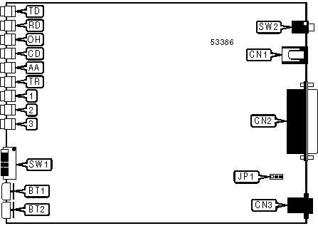
CONNECTIONS | |||
|
Function |
Label |
Function |
Label |
|
Mode button |
BT1 |
Serial port |
CN2 |
|
Talk/Data button |
BT2 |
Telephone line out |
CN3 |
|
DC power in |
CN1 |
Power switch |
SW2 |
Note: BT1 may be used to change the modem's speed when the command set is disabled. | |||
|
USER CONFIGURABLE SETTINGS | ||
|
Setting |
Label |
Position |
|
í Modem is configured for switched line mode |
JP1 |
Pins 1 & 2 closed |
|
Modem is configured for leased line mode |
JP1 |
Pins 2 & 3 closed |
|
í DTR normal (when %F1 set only) |
SW1/1 |
Off |
|
DTR forced high (when %F1 set only) |
SW1/1 |
On |
|
í DSR normal (when %F1 set only) |
SW1/2 |
Off |
|
DSR follows DTR (when %F1 set only) |
SW1/2 |
On |
|
í Test pattern disabled (when #F1 set and SW1/4 off only) |
SW1/3 |
Off |
|
Test pattern enabled (when #F1 set and SW1/4 off only) |
SW1/3 |
On |
|
Auto-answer enabled (when SW1/4 on) |
SW1/3 |
Off |
|
Auto-answer disabled (when SW1/4 on) |
SW1/3 |
On |
|
í Command set enabled |
SW1/4 |
Off |
|
Command set disabled |
SW1/4 |
On |
|
í Analog loopback test disabled (when #F1 set and SW1/4 off only) |
SW1/5 |
Off |
|
Analog loopback test enabled (when #F1 set and SW1/4 off only) |
SW1/5 |
On |
|
Modem will operate in asynchronous mode (when SW1/4 on) |
SW1/5 |
Off |
|
Modem will operate in synchronous mode (when SW1/4 on) |
SW1/5 |
On |
|
í Remote digital loopback test disabled (when #F1 set and SW1/4 off only) |
SW1/6 |
Off |
|
Remote digital loopback test enabled (when #F1 set and SW1/4 off only) |
SW1/6 |
On |
|
Modem will operate in answer mode (when SW1/4 on) |
SW1/6 |
Off |
|
Modem will operate in originate mode (when SW1/4 on) |
SW1/6 |
On |
|
COMMAND SET SELECTION (WHEN %F0 SET ONLY) | ||
|
Setting |
SW1/1 |
SW1/2 |
|
í Asynchronous AT command set |
Off |
Off |
|
Asynchronous V.25bis command set |
Off |
On |
|
Synchronous V.25bis command set in HDLC mode |
On |
Off |
|
Synchronous V.25bis command set in bisynchronous mode |
On |
On |
|
DIAGNOSTIC LED(S) | |||
|
LED |
Color |
Status |
Condition |
|
TD |
Red |
Blinking |
Modem is transmitting data |
|
TD |
Red |
Off |
Modem is not transmitting data |
|
RD |
Red |
Blinking |
Modem is receiving data |
|
RD |
Red |
Off |
Modem is not receiving data |
|
OH |
Red |
On |
Modem is off-hook |
|
OH |
Red |
Off |
Modem is on-hook |
|
CD |
Red |
On |
Carrier signal detected |
|
CD |
Red |
Off |
Carrier signal not detected |
|
AA |
Red |
On |
Auto-answer enabled |
|
AA |
Red |
Off |
Auto-answer disabled |
|
AA |
Red |
Blinking |
Modem is in test mode |
|
TR |
Red |
On |
DTR signal is high |
|
TR |
Red |
Off |
DTR signal is low |
|
DIAGNOSTIC LED(S) (CON’T) | |||
|
1 Status |
2 Status |
3 Status |
Condition |
|
Slow blink |
Off |
Off |
Modem is connected at 300bps |
|
Slow blink |
Off |
On |
Modem is connected at 1200/75bps |
|
Slow blink |
On |
Off |
Modem is connected at 1200bps |
|
Slow blink |
On |
On |
Modem is connected at 2400bps |
|
Off |
On |
On |
Modem is connected at 4800bps |
|
On |
Off |
Off |
Modem is connected at 7200bps |
|
On |
Off |
On |
Modem is connected at 9600bps |
|
On |
On |
Off |
Modem is connected at 12Kbps |
|
On |
On |
On |
Modem is connected at 14.4Kbps |
|
Medium blink |
On |
Off |
Modem is connected at 16.8Kbps |
|
Medium blink |
Off |
On |
Modem is connected at 19.2Kbps |
|
Medium blink |
On |
On |
Modem is connected at 21.6Kbps |
|
Fast blink |
Off |
Off |
Modem is connected at 24Kbps |
|
Fast blink |
On |
Off |
Modem is connected at 26.4Kbps |
|
Fast blink |
On |
On |
Modem is connected at 28.8Kbps |
|
Off |
Off |
Slow blink |
Modem is connected at 2400bps in fax mode |
|
Off |
On |
Slow blink |
Modem is connected at 4800bps in fax mode |
|
On |
Off |
Slow blink |
Modem is connected at 7200bps in fax mode |
|
On |
On |
Slow blink |
Modem is connected at 9600bps in fax mode |
|
On |
Slow blink |
Slow blink |
Modem is connected at 14.4Kbps in fax mode |
|
SUPPORTED STANDARD COMMANDS |
|
Basic AT Commands |
|
+++, ‘comma’, A/ |
|
A, E, H, L, N, P, T, V, W, Z |
|
&D, &F, &G, &P, &R, &S, &T, &W, &X, &Y, &Z |
|
Extended AT Commands |
|
\A, \B, \N, \Q, \T, \X |
|
%C, %E, %Q |
|
Special AT Commands |
|
:E, *H, -K, )M, -Q |
|
S-Registers |
|
S0, S1, S2, S3, S4, S5, S6, S7, S8, S9, S10, S11, S12, S16, S18, S25, S26, S29, S30, S38, S95 |
|
V.25bis Commands |
|
The V.25bis command set is unidentified. |
Note: See MHI help file for complete information. |
|
UNIDENTIFIED COMMANDS | |
|
Command |
Default |
|
F |
Unidentified |
|
\K |
5 |
|
&Q |
Unidentified |
|
#R |
Immediate |
Proprietary AT Command Set
|
AUTO-RANGE TIME | |
|
Type: |
Register |
|
Format: |
AT [cmds] S47=n [cmds] |
|
Default: |
8 |
|
Range: |
1 - 255 |
|
Unit: |
1 second |
|
Description: |
The function of this command is unidentified. |
|
BREAK LENGTH | |
|
Type: |
Register |
|
Format: |
AT [cmds] S43=n [cmds] |
|
Default: |
15 |
|
Range: |
0 - 255 |
|
Unit: |
1 mS |
|
Description: |
Sets the default length of transmitted break signals. |
|
BUFFER FAILSAFE OVERRUN | |
|
Type: |
Register |
|
Format: |
AT [cmds] S82=n [cmds] |
|
Default: |
60 |
|
Range: |
1 - 255 |
|
Unit: |
1 byte |
|
Description: |
The function of this command is unidentified. |
|
BUFFER MAXIMUM LEVEL | |
|
Type: |
Register |
|
Format: |
AT [cmds] S80=n [cmds] |
|
Default: |
15 |
|
Range: |
1 - 19 |
|
Unit: |
5% of the total buffer space |
|
Description: |
Sets the percentage of the buffer that must be full before the modem sends the character or signal to pause the data. |
|
BUFFER MINIMUM LEVEL | |
|
Type: |
Register |
|
Format: |
AT [cmds] S81=n [cmds] |
|
Default: |
3 |
|
Range: |
1 - 19 |
|
Unit: |
5% of the total buffer space |
|
Description: |
Sets the percentage of the buffer that must be empty before the modem sends the character or signal to restart the data. |
|
BUFFER OVERFLOW | |
|
Type: |
Configuration |
|
Format: |
AT [cmds] #On [cmds] |
|
Description: |
Sets the modem's response when a buffer overflows. |
|
Command |
Function |
|
í #O0 |
Modem drops incoming characters when buffer overflows. |
|
#O1 |
Modem disconnects when transmit buffer overflows. |
|
#O2 |
Modem disconnects when receive buffer overflows. |
|
#O3 |
Modem disconnects when either buffer overflows. |
|
CALLBACK DELAY | |
|
Type: |
Register |
|
Format: |
AT [cmds] S27=n [cmds] |
|
Default: |
0 |
|
Range: |
0 - 255 |
|
Unit: |
1 second |
|
Description: |
Sets the amount of time that must elapse between the modem disconnecting and beginning a callback sequence. |
|
CALLING TONE | |
|
Type: |
Configuration |
|
Format: |
AT [cmds] #Cn [cmds] |
|
Description: |
Controls whether the modem will send a V.25 calling tone when originating a call. |
|
Command |
Function |
|
#C0 |
Calling tone disabled. |
|
í #C1 |
Calling tone enabled. |
|
CLOCK START | ||
|
Type: |
Configuration | |
|
Format: |
AT [cmds] &Hn [cmds] | |
|
Description: |
Selects when the modem begins generating a clock signal when in synchronous mode. | |
|
Command |
Function | |
|
í &H0 |
Clock signal always generated. | |
|
&H1 |
Clock signal only generated after modem is connected. | |
|
COMMAND LINE TIMEOUT | |
|
Type: |
Register |
|
Format: |
AT [cmds] S69=n [cmds] |
|
Default: |
60 |
|
Range: |
0 - 255 |
|
Unit: |
1 second |
|
Description: |
The function of this register is unidentified. |
|
COMMAND SET | ||
|
Type: |
Immediate | |
|
Format: |
AT [cmds] #Mn [cmds] | |
|
Description: |
Selects the command set the modem will recognise. | |
|
Command |
Function | |
|
í #M0 |
Asynchronous AT command set enabled. | |
|
#M1 |
Asynchronous V.25bis command set enabled. | |
|
#M2 |
Synchronous V.25bis command set enabled in HDLC mode. | |
|
#M3 |
Synchronous V.25bis command set enabled in bisynchronous mode. | |
|
COMMAND VERIFICATION | |
|
Type: |
Configuration |
|
Format: |
AT [cmds] #Vn [cmds] |
|
Description: |
Selects whether the modem verifies entered commands. |
|
Command |
Function |
|
#V0 |
Command verification disabled. |
|
í #V1 |
Command verification enabled. |
|
COMMUNICATIONS MODE | |
|
Type: |
Configuration |
|
Format: |
AT [cmds] &Mn [cmds] |
|
Description: |
Selects communications mode. |
|
Command |
Mode |
|
í &M0 |
Modem operates in asynchronous mode. |
|
&M1 |
Modem operates in synchronous connect mode and asynchronous off-line command mode. |
|
&M2 |
Modem operates in synchronous mode; DTR dialing enabled. |
|
&M4 |
Modem operates in asynchronous mode; DTR dialing enabled. |
|
CONNECT MESSAGE | |
|
Type: |
Configuration |
|
Format: |
AT [cmds] %Pn [cmds] |
|
Description: |
Sets when DCD is raised compared to when the CONNECT message is displayed. |
|
Command |
Function |
|
í %P0 |
DCD is raised before CONNECT message is displayed. |
|
%P1 |
DCD is raised after CONNECT message is displayed. |
|
CTS SIGNAL | |
|
Type: |
Configuration |
|
Format: |
AT [cmds] %Kn [cmds] |
|
Description: |
Controls the behaviour of the CTS signal. |
|
Command |
Function |
|
í %K0 |
CTS normal. |
|
%K1 |
CTS forced low during dialing and handshaking. |
|
CTS SIGNAL | |
|
Type: |
Configuration |
|
Format: |
AT [cmds] %Rn [cmds] |
|
Description: |
Controls the behaviour of the CTS signal. |
|
Command |
Function |
|
í %R0 |
CTS signal controlled by &R command. |
|
%R1 |
CTS follows RTS. |
|
%R2 |
CTS follows DTR when off-line. |
|
DATA LENGTH | ||
|
Type: |
Configuration | |
|
Format: |
AT [cmds] &Bn [cmds] | |
|
Description: |
Selects the length of data words for the local serial port. | |
|
Command |
Function | |
|
&B0 |
8 bit data words selected. | |
|
&B1 |
9 bit data words selected. | |
|
&B2 |
10 bit data words selected. | |
|
&B3 |
11 bit data words selected. | |
|
í &B4 |
Modem auto-detects 10 or 11 bit word length. | |
|
DCD SIGNAL | |
|
Type: |
Configuration |
|
Format: |
AT [cmds] &Cn [cmds] |
|
Description: |
Controls the behaviour of the DCD signal. |
|
Command |
Function |
|
&C0 |
DCD forced high. |
|
í &C1 |
DCD forced high after carrier signal is detected. |
|
&C2 |
DCD forced high except at disconnect. |
|
&C3 |
DCD forced high for voice mode. |
|
DCD SIGNAL | |
|
Type: |
Configuration |
|
Format: |
AT [cmds] %Tn [cmds] |
|
Description: |
Controls the behaviour of the DCD signal. |
|
Command |
Function |
|
í %T0 |
DCD normal. |
|
%T1 |
DCD forced high. |
|
DES ENCRYPTION | |
|
Type: |
Configuration |
|
Format: |
AT [cmds] #En [cmds] |
|
Description: |
Selects whether the modem will use DES en/decryption on transmitted and received data. |
|
Command |
Function |
|
í #E0 |
DES encryption disabled. |
|
#E1 |
DES encryption enabled. |
|
DIAL | |
|
Type: |
Immediate |
|
Format: |
AT [cmds] D<#>;[cmds] |
|
Description: |
Dials the telephone number indicated according to any modifiers included in the string. |
|
Command |
Function |
|
DF |
Calling tone disabled for this call. |
|
DJ |
MNP10 link will be negotiated at 1200bps for this call. |
|
DK |
MNP10 power level adjustment enabled for this call. |
|
DL |
Re-dial last number. |
|
DM |
Make a LAPM reliable mode connection this call. |
|
DP |
Pulse dialing enabled. |
|
DR |
Answer mode enabled; originate mode disabled following handshake initiation. |
|
DS=n |
Dial stored telephone number n. |
|
DT |
Tone dialing enabled. |
|
DW |
Dialing resumed following dial tone detection. |
|
D, |
Dialing paused for amount of time specified in S8 register. |
|
D! |
Flash function initiated. Modem commanded to go off-hook for specified time before returning on-hook. |
|
D@ |
Wait for Quiet Answer function enabled. Modem waits until a "quiet answer," a ring-back signal followed by silence up to the time specified in S7, is received prior to executing the rest of the dial string. |
|
D^ |
Calling tone disabled for this call. |
|
D; |
Modem returned to idle state after dialing. The semicolon can only be placed at the end of the dial command. |
|
DIRECT CALLING | ||
|
Type: |
Configuration | |
|
Format: |
AT [cmds] #Dn [cmds] | |
|
Description: |
Selects whether the modem may use V.25bis direct calling procedures. | |
|
Command |
Function | |
|
í #D0 |
V.25bis direct calling procedures disabled. | |
|
#D1 |
V.25bis direct calling procedures enabled. | |
|
DIRECT MODE FALLBACK | ||
|
Type: |
Configuration | |
|
Format: |
AT [cmds] \Jn [cmds] | |
|
Description: |
Selects whether the modem is allowed to fall back to direct mode. | |
|
Command |
Function | |
|
í \J0 |
Direct mode fallback disabled. | |
|
\J1 |
Direct mode fallback enabled. | |
|
DISCONNECT CAUSE | |
|
Type: |
Register (read-only) |
|
Format: |
AT [cmds] S42? [cmds] |
|
Description: |
The meanings of the values for this register are unidentified. |
|
DISCONNECT CAUSE - PREVIOUS CALL | |
|
Type: |
Register (read-only) |
|
Format: |
AT [cmds] S74? [cmds] |
|
Description: |
The meanings of the values for this register are unidentified. |
|
DISCONNECT DELAY | |
|
Type: |
Configuration |
|
Format: |
AT [cmds] %Dn [cmds] |
|
Default: |
0 |
|
Range: |
Unidentified |
|
Unit: |
1 second |
|
Description: |
Sets the delay before disconnection. |
|
DISPLAY CONFIGURATION AND STATISTICS | |
|
Type: |
Immediate |
|
Format: |
AT [cmds] \S [cmds] |
|
Description: |
Displays the settings of all commands and statistics about the current connection. |
|
DISPLAY INFORMATION | |
|
Type: |
Immediate |
|
Format: |
AT [cmds] In [cmds] |
|
Description: |
Displays information requested about the modem. |
|
Command |
Function |
|
I0 |
Displays product identification code. |
|
I1 |
Displays ROM checksum. |
|
I2 |
Tests and displays ROM checksum result. |
|
I3 |
Displays modem manufacturer. |
|
I4 |
Displays firmware revision and release date. |
|
I5 |
Displays manufacturer information. |
|
I9 |
Displays firmware model. |
|
DISPLAY PROFILES | |
|
Type: |
Immediate |
|
Format: |
AT [cmds] &Vn [cmds] |
|
Description: |
Displays the configuration profile indicated. |
|
Command |
Function |
|
&V |
Displays current command settings. |
|
&V0 |
Displays stored profile 0. |
|
&V1 |
Displays stored profile 1. |
|
&V2 |
Displays stored profile 2. |
|
&V3 |
Displays stored profile 3. |
|
&V8 |
Displays the differences between the active and the default profile. |
|
DSR SIGNAL | |
|
Type: |
Configuration |
|
Format: |
AT [cmds] %Sn [cmds] |
|
Description: |
Controls the behaviour of the DSR signal. |
|
Command |
Function |
|
í %S0 |
DSR normal. |
|
%S1 |
DSR follows DTR. |
|
EXTENDED RESULT CODES | |
|
Type: |
Configuration |
|
Format: |
AT [cmds] %Un [cmds] |
|
Description: |
Selects which extended result codes the modem will display. |
|
Command |
Function |
|
í %U0 |
/REL result codes will be displayed for all error correction connections. |
|
%U1 |
V.42 result codes will be displayed. |
|
%U2 |
V.42 and V.42bis, MNP2 - 5, MNP10, and DES result codes will be displayed. |
|
EXTENDED RESULT CODES - /REL | |
|
Type: |
Configuration |
|
Format: |
AT [cmds] \Vn [cmds] |
|
Description: |
Selects /REL extended result codes. |
|
Command |
Function |
|
í \V0 |
/REL result codes disabled. |
|
\V1 |
/REL result codes enabled. |
|
\V8 |
Extended result codes enabled. |
|
\V9 |
Extended result codes enabled with diagnostic information. |
|
FLASH DIAL MODIFIER TIME | |
|
Type: |
Register |
|
Format |
AT [cmds] S100=n [cmds] |
|
Default: |
5 |
|
Range: |
1 - 10 |
|
Unit: |
.1 second |
|
Description: |
Time the modem will go on-hook upon receiving the ! dial modifier in dial string. |
|
FLOW CONTROL | |
|
Type: |
Configuration |
|
Format: |
AT [cmds] &Kn [cmds] |
|
Description: |
Selects the type of flow control the modem will use. |
|
Command |
Function |
|
&K0 |
Flow control disabled. |
|
&K3 |
RTS/CTS flow control enabled. |
|
&K4 |
XON/XOFF flow control enabled. |
|
&K5 |
Transparent XON/XOFF flow control enabled. |
|
í &K9 |
Failsafe flow control enabled. |
|
FRONT PANEL SWITCHES SW1/1 AND SW1/2 | ||
|
Type: |
Configuration | |
|
Format: |
AT [cmds] %Fn [cmds] | |
|
Description: |
Controls the function of front panel switches SW1/1 and SW1/2. | |
|
Command |
Function | |
|
%F0 |
Switches SW1/1 and SW1/2 control V.25bis settings. | |
|
í %F1 |
Switches SW1/1 and SW1/2 control DSR and DTR settings. | |
|
FRONT PANEL TESTS | ||
|
Type: |
Configuration | |
|
Format: |
AT [cmds] #Fn [cmds] | |
|
Description: |
Selects whether the front panel switches may be used to cause the modem to enter a test mode. | |
|
Command |
Function | |
|
í #F0 |
Front panel test modes disabled. | |
|
#F1 |
Front panel test modes enabled. | |
|
HELP | |
|
Type: |
Immediate |
|
Format: |
AT [cmds] ? [cmds] |
|
Description: |
Displays help on the modem's commands. |
|
HELP SCREEN LENGTH | |
|
Type: |
Register |
|
Format: |
AT [cmds] S97=n [cmds] |
|
Default: |
24 |
|
Range: |
1 - 255 |
|
Unit: |
1 line |
|
Description: |
Sets the number of lines of text of the help screen the modem will display before pausing. |
|
HELP SCREEN WIDTH | |
|
Type: |
Register |
|
Format: |
AT [cmds] S96=n [cmds] |
|
Default: |
80 |
|
Range: |
1 - 255 |
|
Unit: |
1 column |
|
Description: |
Sets the number of characters wide the modem will format the help screen to display. |
|
INTERRUPT DIALING SEQUENCE | |
|
Type: |
Configuration |
|
Format: |
AT [cmds] &Nn [cmds] |
|
Description: |
Selects whether a dial or connect sequence may be interrupted by user input. |
|
Command |
Function |
|
&N0 |
Dial interrupt disabled. |
|
í &N1 |
Dial interrupt enabled. |
|
LED MODE | |
|
Type: |
Configuration |
|
Format: |
AT [cmds] %Mn [cmds] |
|
Description: |
Sets what the front-panel LEDs indicate. |
|
Command |
Function |
|
í %M0 |
LEDs indicate line speed. |
|
%M1 |
LEDs indicate line quality, V.42 and MNP errors, and flow control. |
|
LINE TYPE | ||
|
Type: |
Configuration | |
|
Format: |
AT [cmds] &Ln [cmds] | |
|
Description: |
Selects the type of telephone line the modem is connected to. | |
|
Command |
Function | |
|
í &L0 |
Modem is connected to switched line. | |
|
&L1 |
Modem is connected to leased line. | |
|
&L2 |
Modem is connected to leased line in auto-originate mode. | |
|
&L3 |
Modem is connected to leased line in auto-answer mode. | |
|
LOCAL SERIAL PORT SPEED | |
|
Type: |
Configuration |
|
Format: |
AT [cmds] Rn [cmds] |
|
Description: |
Sets the speed of the local serial port. |
|
Command |
Function |
|
R9 |
Set local serial port speed to 9600bps. |
|
R14 |
Set local serial port speed to 14.4Kbps. |
|
R19 |
Set local serial port speed to 19.2Kbps. |
|
R28 |
Set local serial port speed to 28.8Kbps. |
|
R38 |
Set local serial port speed to 38.4Kbps. |
|
R57 |
Set local serial port speed to 57.6Kbps. |
|
R115 |
Set local serial port speed to 115.2Kbps. |
|
R230 |
Set local serial port speed to 230.4Kbps. |
|
LOCAL SERIAL PORT SPEED - NON-STANDARD | ||
|
Type: |
Configuration | |
|
Format: |
AT [cmds] %Nn [cmds] | |
|
Description: |
Selects non-standard serial port speeds above 14.4Kbps. | |
|
Command |
Function | |
|
í %N0 |
Standard serial port speeds used. | |
|
%N1 |
Speeds above 14.4Kbps are 20.8Kbps, 41.6Kbps, and 62.4Kbps. | |
|
%N2 |
Speeds above 14.4Kbps are 19.2Kbps, 28.8Kbps, 38.4Kbps, and 51.2Kbps. | |
|
LOCAL SERIAL PORT SPEED - V.25bis MODE | |
|
Type: |
Configuration |
|
Format: |
AT [cmds] #Qn [cmds] |
|
Description: |
Sets the speed of the local serial port when in V.25bis mode. |
|
Command |
Function |
|
#Q9 |
Set local serial port speed to 9600bps. |
|
#Q14 |
Set local serial port speed to 14.4Kbps. |
|
#Q19 |
Set local serial port speed to 19.2Kbps. |
|
#Q28 |
Set local serial port speed to 28.8Kbps. |
|
#Q38 |
Set local serial port speed to 38.4Kbps. |
|
#Q57 |
Set local serial port speed to 57.6Kbps. |
|
#Q115 |
Set local serial port speed to 115.2Kbps. |
|
#Q230 |
Set local serial port speed to 230.4Kbps. |
|
MNP10 | ||
|
Type: |
Configuraion | |
|
Format: |
AT [cmds] #Kn [cmds] | |
|
Description: |
Selects whether the modem will attempt to use MNP10 error correction. | |
|
Command |
Function | |
|
#K0 |
MNP10 disabled. | |
|
í #K1 |
MNP10 enabled. | |
|
#K2 |
MNP10 enabled for cellular connections only. | |
|
MNP10 LINK NEGOTIATION | |
|
Type: |
Configuration |
|
Format: |
AT [cmds] %Hn [cmds] |
|
Description: |
Sets the speed at which MNP10 link negotiation will occur. |
|
Command |
Function |
|
í %H0 |
Link will be negotiated at speed set by B command. |
|
%H1 |
Link will be negotiated at 1200bps. |
|
%H2 |
Link will be negotiated at 4800bps. |
|
%H3 |
Link will be negotiated at 9600bps. |
|
%H9 |
Link will be negotiated at speed set by B command and modem will not fall forward. |
|
ON-LINE | |
|
Type: |
Immediate |
|
Format: |
AT [cmds] On |
|
Description: |
Instructs the modem to return to the on-line state. |
|
Note: |
O3 through O7 are only valid for V.32 and V.32bis connections. |
|
Command |
Function |
|
O0 |
Return to on-line state. |
|
O1 |
Return to on-line state and initiate retrain sequence. |
|
O2 |
Initiate retrain sequence. |
|
O3 |
Re-negotiate speed to 4800bps and return to on-line state. |
|
O4 |
Re-negotiate speed to 7200bps and return to on-line state. |
|
O5 |
Re-negotiate speed to 9600bps and return to on-line state. |
|
O6 |
Re-negotiate speed to 12Kbps and return to on-line state. |
|
O7 |
Re-negotiate speed to 14.4Kbps and return to on-line state. |
|
PROTOCOL/SPEED | |
|
Type: |
Configuration |
|
Format: |
AT [cmds] Bn [cmds] |
|
Description: |
Selects the protocol and speed the modem will attempt to connect at. |
|
Command |
Function |
|
B0 |
Select protocol specified by #B at 1200bps. |
|
B1 |
Auto-detect the highest common connect speed. |
|
B2 |
Select protocol specified by #B at 1200bps. |
|
B3 |
Select V.21 at 300bps speed. |
|
B4 |
Select Bell 103 at 300bps speed. |
|
B5 |
Select V.23 at 1200/75bps speed. |
|
B6 |
Select V.22 at 1200bps speed. |
|
B7 |
Select Bell 212A at 1200bps speed. |
|
B8 |
Select V.22bis at 2400bps speed. |
|
B9 |
Auto-detect the highest common connect speed. |
|
B10 |
Select V.32 at 4800bps speed. |
|
B11 |
Select V.32bis at 7200bps speed. |
|
B12 |
Select V.32bis uncoded at 9600bps speed. |
|
B13 |
Select V.32bis at 9600bps speed. |
|
B14 |
Select V.32bis at 12Kbps speed. |
|
B15 |
Select V.32bis at 14.4Kbps speed. |
|
B16 |
Select V.34 at 14.4Kbps speed. |
|
B17 |
Select V.34 at 16.8Kbps speed. |
|
B18 |
Select V.34 at 19.2Kbps speed. |
|
B19 |
Select V.34 at 21.6Kbps speed. |
|
B20 |
Select V.34 at 24Kbps speed. |
|
B21 |
Select V.34 at 26.4Kbps speed. |
|
B22 |
Select V.34 at 28.8Kbps speed. |
|
PROTOCOL/SPEED MODIFIER | |
|
Type: |
Configuration |
|
Format: |
AT [cmds] #Bn [cmds] |
|
Description: |
Selects the communication protocol for low-speed data calls. |
|
Command |
Protocol |
|
í #B0 |
B2 indicates modem will use ITU-T V.22 at 1200bps; B0 indicates modem will use V.23 at 1200bps. |
|
#B1 |
B0 indicates modem will use ITU-T V.22 at 1200bps; B2 indicates modem will use V.23 at 1200bps. |
|
REMOTE CONFIGURATION | |
|
Type: |
Configuration |
|
Format: |
AT [cmds] #An [cmds] |
|
Description: |
Sets whether the modem will allow remote configuration sessions. |
|
Command |
Function |
|
#A0 |
Remote configuration disabled. |
|
#A1 |
Remote configuration enabled. |
|
í #A2 |
Remote configuration enabled and configuration password required. |
|
REMOTE CONFIGURATION CHARACTER | |
|
Type: |
Register |
|
Format: |
AT [cmds] S67=n [cmds] |
|
Default: |
42 |
|
Range: |
0 - 127 |
|
Unit: |
1 ASCII character |
|
Description: |
Defines the character that, when sent four times within the guard time set by S12, will notify the modem that a remote configuration session has been requested. |
|
REMOTE CONFIGURATION SEQUENCE GUARD TIME | |
|
Type: |
Register |
|
Format |
AT [cmds] S66=n [cmds] |
|
Default: |
10 |
|
Range: |
1 - 255 |
|
Unit: |
.1 second |
|
Description: |
Maximum allowable time between remote configuration character sequence initiation and completion for the remote configuration sequence to be executed. |
|
REMOTE CONFIGURATION SEQUENCE | |
|
Type: |
Immediate |
|
Format: |
**** <WAIT> |
|
Description: |
Initiates the remote configuration escape sequence, requesting to begin a remote configuration session with the remote modem. The modem must receive the four characters set with the S67 command within the time allotted by S66. |
|
Note: |
Do not precede this command with AT. |
|
RESULT CODES | |
|
Type: |
Configuration |
|
Format: |
AT [cmds] Qn [cmds] |
|
Description: |
Enables modem to send result codes to the DTE. |
|
Command |
Function |
|
í Q0 |
Result codes enabled. |
|
Q1 |
Result codes disabled. |
|
Q2 |
Result codes enabled in originate mode only. |
|
RESULT CODES | |
|
Type: |
Configuration |
|
Format: |
AT [cmds] Xn [cmds] |
|
Description: |
Enables selection of tone detection and associated result code format options. |
|
Command |
Function |
|
X0 |
Busy and dial tone detection disabled; basic result codes only enabled. |
|
X1 |
Busy and dial tone detection disabled; basic result codes with connect speed enabled. |
|
X2 |
Busy tone detection disabled, dial tone detection enabled; basic result codes with connect speed enabled. |
|
X3 |
Busy tone detection enabled, dial tone detection disabled; basic result codes with connect speed enabled. |
|
X4 |
Busy and dial tone detection enabled; basic result codes with connect speed enabled. |
|
í X5 |
Busy and dial tone detection enabled; basic result codes with connect speed enabled; RINGING response enabled.. |
|
X6 |
Busy tone detection enabled, dial tone detection disabled; basic result codes with connect speed enabled; RINGING response enabled. |
|
SECURITY MENU MODE | |
|
Type: |
Immediate |
|
Format: |
AT [cmds] #S |
|
Description: |
Commands the modem to enter security menu mode. |
|
SPEAKER MODE | |
|
Type: |
Configuration |
|
Format: |
AT [cmds] Mn [cmds] |
|
Description: |
Selects various speaker options. |
|
Command |
Function |
|
M0 |
Speaker disabled. |
|
í M1 |
Speaker enabled until carrier signal detected. |
|
M2 |
Speaker enabled. |
|
M3 |
Speaker enabled following dialing, then disabled after carrier signal detected. |
|
M4 |
Speaker enabled during dialing, answering, and line speed changes. |
|
SYNCHRONOUS MODE ENCODING | ||
|
Type: |
Configuration | |
|
Format: |
AT [cmds] #Nn [cmds] | |
|
Description: |
Selects the type of character encoding the modem will use when in synchronous V.25bis mode. | |
|
Command |
Function | |
|
í #N0 |
Modem will use NRZ encoding. | |
|
#N1 |
Modem will use NRZI encoding. | |
|
TRANSMISSION LEVEL | |
|
Type: |
Configuration |
|
Format: |
AT [cmds] %Ln [cmds] |
|
Default: |
Unidentified |
|
Range: |
11 - 19 |
|
Unit: |
-1 dBm |
|
Description: |
Sets the signal level for transmission. If no value is given the current transmission level is displayed. |
|
V.13 REMOTE RTS | |
|
Type: |
Configuration |
|
Format: |
AT [cmds] *Rn [cmds] |
|
Description: |
Toggles V.13 remote RTS signaling. |
|
V.22bis AND BELOW EQM THRESHHOLD | |
|
Type: |
Register |
|
Format: |
AT [cmds] S45=n [cmds] |
|
Default: |
98 |
|
Range: |
0 - 255 |
|
Unit: |
Unidentified |
|
Description: |
Sets the quality threshhold for connections at V.22bis and below. |
|
V.22bis ON LEASED LINE | ||
|
Type: |
Configuration | |
|
Format: |
AT [cmds] #In [cmds] | |
|
Description: |
Selects whether the modem will use the switched line standard for V.22bis modulation when operating over a leased line connection. | |
|
Command |
Function | |
|
í #I0 |
Modem will use leased line V.22bis over leased lines. | |
|
#I1 |
Modem will use switched line V.22bis over leased lines. | |
|
V.25bis CHARACTER SET | ||
|
Type: |
Configuration | |
|
Format: |
AT [cmds] #Un [cmds] | |
|
Description: |
Selects the character set the modem will use when in V.25bis mode. | |
|
Command |
Function | |
|
í #U0 |
Modem will use ASCII characters. | |
|
#U1 |
Modem will use EBCDIC characters. | |
|
V.25bis IGNORE INCOMING CALL | |
|
Type: |
Register |
|
Format: |
AT [cmds] S71=n [cmds] |
|
Default: |
0 |
|
Range: |
0 - 30 |
|
Unit: |
1 second |
|
Description: |
The function of this register is unidentified. |
|
V.32 AND V.32bis EQM THRESHHOLD | |
|
Type: |
Register |
|
Format: |
AT [cmds] S33=n [cmds] |
|
Default: |
3 |
|
Range: |
0 - 255 |
|
Unit: |
Unidentified |
|
Description: |
Sets the quality threshhold for connections at V.32 and V.32bis. |
|
V.34 MODE | |
|
Type: |
Configuration |
|
Format: |
AT [cmds] *Cn [cmds] |
|
Description: |
Selects whether the modem will use V.34 mode. |
|
Command |
Function |
|
í *C0 |
V.34 mode enabled. |
|
*C1 |
V.34 mode disabled; V.FC used for 28.8Kbps connections.. |
|
V.42 DETECTION PHASE | |
|
Type: |
Configuration |
|
Format: |
AT [cmds] #Jn [cmds] |
|
Description: |
Selects whether the modem will go through the V.42 detection phase. |
|
Command |
Function |
|
#J0 |
V.42 detection phase disabled. |
|
í #J1 |
V.42 detection phase enabled. |
|
V.42 DETECTION PHASE TIME | |
|
Type: |
Register |
|
Format: |
AT [cmds] S62=n [cmds] |
|
Default: |
75 |
|
Range: |
0 - 255 |
|
Unit: |
10 mS |
|
Description: |
Sets the length of the V.42 detection phase. |
|
VOICE - DEAD MAN TIMEOUT | |
|
Type: |
Register |
|
Format: |
AT [cmds] S105=n [cmds] |
|
Default: |
30 |
|
Range: |
0 - 255 |
|
Unit: |
1 second |
|
Description: |
The function of this command is unidentified. |
|
WELCOME MESSAGE | |
|
Type: |
Configuration |
|
Format: |
AT [cmds] *Wxxxx|xxxx [cmds] |
|
Description: |
Sets the welcome message displayed to incoming connections. The vertical bar (|) character may be used to specify line breaks. The message must be 80 characters or less. |
|
WELCOME MESSAGE DISPLAY | |
|
Type: |
Configuration |
|
Format: |
AT [cmds] %Wn [cmds] |
|
Description: |
Selects whether the modem will display the welcome message to incoming connections. |
|
Note: |
See the *W command for more information. |
|
Command |
Function |
|
í %W0 |
Welcome message will not be displayed. |
|
%W1 |
Welcome message will be displayed. |