SIIG, INC.
DASH 28.8I FAX/MODEM EXTERNAL
|
Modem Type |
Data (synchronous/asynchronous)/Fax |
|
Maximum Data Rate |
28.8Kbps |
|
Maximum Fax Rate |
14.4Kbps |
|
Data Bus |
External |
|
Fax Class |
Class I & II |
|
Data Modulation Protocol |
Bell 103A/212A ITU-T V.21, V.22, V.22bis, V.23, V.32, V.32bis, V.34 Rockwell V.FC |
|
Fax Modulation Protocol |
ITU-T V.17, V.21CH2, V.27ter, V.29 |
|
Error Correction/Compression |
MNP5, V.42, V.42bis |
|
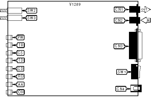
CONNECTIONS | |||
|
Purpose |
Location |
Purpose |
Location |
|
Line out |
CN1 |
Power switch |
SW1 |
|
Line in |
CN2 |
Data/Voice |
SW2 |
|
RS-232/422 |
CN3 |
Answer/Originate |
SW3 |
|
AC power |
CN4 | ||
|
DIAGNOSTIC LED(S) | |||
|
LED |
Color |
Status |
Condition |
|
PW |
Red |
On |
Power is on. |
|
PW |
Red |
Off |
Power is off |
|
TR |
Red |
On |
DTR signal is high |
|
TR |
Red |
Off |
DTR signal is low |
|
CS |
Red |
On |
CTS signal is high |
|
CS |
Red |
Off |
CTS signal is low |
|
TD |
Red |
Blinking |
Modem is transmitting data |
|
TD |
Red |
Off |
Modem is not transmitting data |
|
CD |
Red |
On |
Carrier signal detected |
|
CD |
Red |
Off |
Carrier signal not detected |
|
RD |
Red |
Blinking |
Modem is receiving data |
|
RD |
Red |
Off |
Modem is not receiving data |
|
AA |
Red |
On |
Auto-answer enabled |
|
AA |
Red |
Off |
Auto-answer disabled |
|
AA |
Red |
Blinking |
Phone is ringing |
|
OH |
Red |
On |
Modem is off-hook |
|
OH |
Red |
Off |
Modem is on-hook |
Proprietary AT Command Set
|
AUTO-RETRAIN - FALLBACK/FALLFORWARD | |
|
Type: |
Configuration |
|
Format: |
AT [cmds] %En [cmds] |
|
Example: |
AT %E1 <CR> |
|
Description: |
Controls auto-retrain mode and fallback/fall forward. |
| Command |
Function |
| » %E0 |
Auto-retrain disabled. |
| %E1 |
Auto-retrain enabled. |
| %E2 |
Fallback/fall forward enabled. |
|
BIT-MAPPED REGISTERS | |
|
Register |
Default |
|
S14 |
138 |
|
S16 |
0 |
|
S21 |
0 |
|
S23 |
54 |
|
S27 |
9 |
|
S28 |
0 |
|
S31 |
2 |
|
S36 |
7 |
|
S40 |
105 |
|
S41 |
3 |
|
S82 |
128 |
|
S91 |
10 |
|
S92 |
10 |
|
S95 |
0 |
|
S201 |
58 |
|
BREAK TYPE | |||
|
Type: |
Configuration | ||
|
Format: |
AT [cmds] \Kn [cmds] | ||
|
Example: |
AT \K1 <CR> | ||
|
Description: |
Configures action of break signal. | ||
|
Command |
Break from DTE |
Break received from remote modem | |
|
\K0 |
Online command mode enabled, send no break to remote modem. |
Buffers cleared, break sent to DTE. | |
|
\K1 |
Break sent to remote modem and buffered cleared. |
Buffers cleared, break sent to DTE. | |
|
\K2 |
Online command mode enabled, send no break to remote modem. |
Break sent immediately to DTE. | |
|
\K3 |
Send break to remote modem immediately. |
Break sent immediately to DTE. | |
|
\K4 |
Online command mode enabled, send no break to remote modem. |
Break sent with received data to the DTE. | |
|
\K5 |
Send break with transmitted data. |
Break sent with received data to the DTE. | |
|
CONNECT MODE | |
|
Type: |
Configuration |
|
Format: |
AT [cmds] \Nn [cmds] |
|
Example: |
AT \N1 DT555-1212 <CR> |
|
Description: |
Sets connect mode. |
| Command |
Function |
| \N0 |
Normal mode enabled. |
| \N1 |
Serial interface enabled |
| \N2 |
Reliable mode enabled. |
| \N3 |
Auto-reliable mode enabled. |
| \N4 |
LAPM mode enabled. |
| \N5 |
MNP mode enabled. |
|
FLOW CONTROL CHARACTER - XON | |
|
Type: |
Register |
|
Format: |
AT [cmds] S32=n [cmds] |
|
Example: |
AT S32=20 <CR> |
|
Default: |
17 |
|
Range: |
0 - 255 |
|
Unit: |
ASCII |
|
Description: |
Sets the character used to represent XON. |
|
FLOW CONTROL CHARACTER - XOFF | |
|
Type: |
Register |
|
Format: |
AT [cmds] S33=n [cmds] |
|
Example: |
AT S33=20 <CR> |
|
Default: |
19 |
|
Range: |
0 - 255 |
|
Unit: |
ASCII |
|
Description: |
Sets the character used to represent XOFF. |
|
HDLC ADDRESS | |
|
Type: |
Register |
|
Format: |
AT [cmds] S20=n [cmds] |
|
Example: |
AT S20=6 <CR> |
|
Default: |
0 |
|
Range: |
0 - 255 |
|
Unit: |
N/A |
|
Description: |
Sets the HDLC address/BSC character. |
|
DISPLAY LINE SIGNAL LEVEL | |
|
Type: |
Immediate |
|
Format: |
AT [cmds] %L [cmds] |
|
Example: |
AT %L &W <CR> |
|
Description: |
Displays a value of the received line signal level. |
|
DISPLAY LINE SIGNAL QUALITY | |
|
Type: |
Immediate |
|
Format: |
AT [cmds] %Q [cmds] |
|
Example: |
AT %Q &W <CR> |
|
Description: |
Displays line signal quality. |
|
FLOW CONTROL | |
|
Type: |
Configuration |
|
Format: |
AT [cmds] \Gn [cmds] |
|
Example: |
AT \G1 &K3 <CR> |
|
Description: |
Selects modem port flow control. |
| Command |
Function |
| » \G0 |
Flow control disabled. |
| \G1 |
Flow control enabled. |
|
MODULATION SELECTION | |
|
Type: |
Configuration |
|
Format: |
AT [cmds] +MS=xx,y,zzz,aaa [cmds] |
|
Example: |
AT +MS11,1,300,28800 &W <CR> |
|
Description: |
Sets options for active protocol. The transfer rates specified by z and a must be valid for the protocol selected. |
| Command |
Function |
| x=0 |
V.21 |
| x=1 |
V.22 |
| x=2 |
V.22bis |
| x=3 |
V.23 |
| x=9 |
V.32 |
| x=10 |
V.32bis |
| » x=11 |
V.34 |
| x=64 |
Bell 103A |
| x=69 |
Bell 212A |
| x=74 |
V.FC |
|
y =0 |
Automode disabled. |
|
y =1 |
Auto-detect highest speed enabled. |
|
z, a =300 |
Set minimum or maximum transfer rate at 300bps, respectively. |
|
z, a =1200 |
Set minimum or maximum transfer rate at 1200bps, respectively. |
|
z, a =2400 |
Set minimum or maximum transfer rate at 2400bps, respectively. |
|
z, a =4800 |
Set minimum or maximum transfer rate at 4800bps, respectively. |
|
z, a =7200 |
Set minimum or maximum transfer rate at 7200bps, respectively. |
|
z, a =9600 |
Set minimum or maximum transfer rate at 9600bps, respectively. |
|
z, a =12000 |
Set minimum or maximum transfer rate at 12000bps, respectively. |
|
z, a =14400 |
Set minimum or maximum transfer rate at 14400bps, respectively. |
|
z, a =16800 |
Set minimum or maximum transfer rate at 16800bps, respectively. |
|
z, a =19200 |
Set minimum or maximum transfer rate at 19200bps, respectively. |
|
z, a =21600 |
Set minimum or maximum transfer rate at 21600bps, respectively. |
|
z, a =24000 |
Set minimum or maximum transfer rate at 24000bps, respectively. |
|
z, a =26400 |
Set minimum or maximum transfer rate at 26400bps, respectively. |
|
z, a =28800 |
Set minimum or maximum transfer rate at 28800bps, respectively. |
|
MODULATION SELECTION DISPLAY | |
|
Type: |
Immediate |
|
Format: |
AT [cmds] +MS? |
|
Example: |
AT &V +MS? <CR> |
|
Description: |
Displays modulation, automode, minimum rate and maximum rate settings |
|
V.42 HANDSHAKE OPTIONS | |
|
Type: |
Register |
|
Format: |
AT [cmds] S48=n [cmds] |
|
Example: |
AT S48=7 <CR> |
|
Default: |
7 |
|
Range: |
0, 7, or 128 |
|
Description: |
Controls the V.42 handshake sequence. |
|
Command |
Function |
| S48=0 |
V.42 negotiation disabled. |
| » S48=7 |
V.42 negotiation enabled. |
| S48=128 |
V.42 disabled; fallback according to S36. |